The schematic ladder diagram can be created first and the physical panel layout created from the schematic drawing.
Each symbol shown on the schematic ladder diagrams can map to a scaled, physical representation on the panel layout drawings. The physical layout drawing might be a control panel enclosure door layout. The door layout shows where to mount each component and can indicate the size of the hole in the sheet metal door for mounting.
Example
For example, pilot light components come in many styles, sizes, and ratings from dozens of vendors. On the schematic ladder diagrams, all pilot lights of a given type are identified by the same schematic symbol whether they are miniature pilot lights or a large, explosion projected pilot light. It is on the physical panel layouts where the pilot lights are shown as they actually look and in actual size (that is, the physical footprint representation).
Look at the three pilot light symbols shown in this schematic drawing.
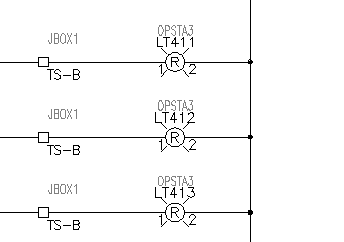
LT411 and LT413 are assigned an Allen-Bradley part number for a 30-mm pilot light (catalog part number 800H-PR16R). LT412 is given a part number for a smaller, 22.5-mm pilot light (catalog part number 800MR-P16RS). The manufacturer and catalog part number assignments are carried on invisible attributes MFG and CAT on each instance of the red pilot light symbol. All three symbols look the same on the schematic since they are the same AutoCAD block symbol. The difference is the assigned part number attribute values that each carries.
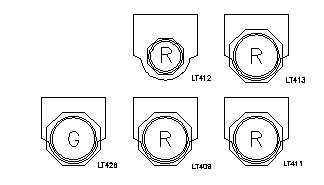
The three red pilot lights are represented as footprints in the panel layout as shown. Notice that LT412 (the 22.5-mm pilot light) appears smaller than the others.
Footprint Mapping
On the physical panel layout drawing, these pilot light symbols are inserted as footprint blocks using the Insert Footprint (Schematic List) tool.
AutoCAD Electrical toolset knows which physical representation block symbol to use for each instance of the pilot light schematic symbol based on the manufacturer and part number assignments applied to the MFG/CAT attributes. The vendor name and part number are mapped to the correct footprint drawing (.dwg) file. This drawing is then inserted as a block on the panel layout drawing.
There are two key elements that make this work:
- Vendor footprint library (.dwg) files - two symbols from this library are shown here. They are for Allen-Bradley red pilot lights 30 mm and 22.5-mm styles respectively.

- Footprint mapping file (footprint_lookup.mdb) - a table is assigned to each manufacturer.