As Circuit Builder dynamically builds the circuit, a circuit element selection may require a conditional component insertion. For example, there may be an option to insert either a “start” push button or a N.O. relay contact at the insertion point of a marker block. If a momentary push button is selected then a “seal” contact should be inserted around the push button at the location marked with a separate marker block. However, if the N.O. relay contact option is selected, then no seal contact is needed and wires must be trimmed or removed.
- Open the circuit template drawing that contains the marker block for the selected component, for example the momentary push button. Take note of the value of its ORDER attribute.
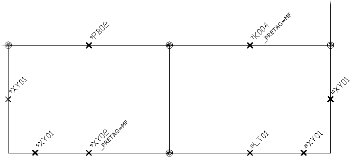
- Find the wire that should receive the conditional component. Add a marker block with the same ORDER attribute value.
- Assign a unique CODE attribute value to this conditional marker block, for example “XY02”.
- Find the wires to remove or trim if the conditional component is not needed.
- Add marker blocks on each of these wire segments. Edit the ORDER attribute value to match the one on the marker block for the conditional component.
- Assign the same CODE value to each wire marker block, for example “XY01”. This CODE value should not be the same as the one assigned to the conditional component marker block.
- Save the circuit template drawing.
- Open the Circuit Builder spreadsheet, ace_circuit_builder.xls.
- Find the circuit CATEGORY and TYPE, for example CATEGORY: 3ph Motor Circuit and TYPE: Horizontal - FVNR - non reversing.
- Open the circuit code sheet with the same name as the SHEET_NAME value, for example SHEET_NAME: 3ph_H.
- Find the optional component, for example CODE: PB02, COMMENTS: Start, UI_PROMPT_LIST: Start.
- Edit the API call in the COMMAND_LIST column for the option that would require the conditional insert. Multiple API calls can be used to insert multiple components. For example:
(c:ace_cb_insym #xyz nil "HPB11" #scl 8 nil)(c:ace_cb_insym "XY02" nil "HMS21" #scl 8 nil)
Note the difference in the second call. Instead of passing the #xyz global variable name that carries the XY coordinate of the main marker block, it passes the "XY02" code name. This means that the "HMS21" symbol will insert wherever marker block "XY02" is located in the inserted template.
- Edit the API call in the COMMAND_LIST column for the option that requires a wire trim or removal. For example:
(c:ace_cb_trim "XY01" nil) where “XY01” is the CODE attribute value assigned to each wire marker block.
Instead of passing the XY coordinate as the first argument, the "XY01" code name is passed. It instructs Circuit Builder to find all marker blocks with CODE attribute value "XY01" and with the target ORDER value and trim or remove their underlying wires
Note: See the API documentation for more information. - Save the spreadsheet.