The default build direction for a multi-pole component is down for horizontal bus wires, and left to right for vertical bus wires. You can override the default build direction.
- Open the circuit template drawing that contains the marker block for the multi-pole component.
- Find the correct marker block for the component.
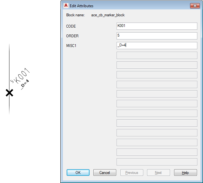
- Edit its MISC1 attribute value using the format “_D={digit}”, where 1=build left to right, 2=build up, 4=build right to left, and 8=build down.
For example, if the template has a vertical 3-phase bus and the disconnection means that marker block is located over the right-hand wire, give its MISC1 attribute a value of "_D=4". It causes the child poles of the multi-pole insert to move to the left to pick up the remaining two bus wires.
 Note: The MISC1 attribute value can contain multiple special text flags which direct Circuit Builder to handle the component or underlying wire in a special way. When you add new values, do not overwrite any other special flag values. Separate each one with a semicolon.
 - Save the circuit template drawing.