Use Terminal Strip Editor to manage terminals, edit terminal properties, associate terminals, and insert the graphical terminal strip.
Terminal blocks connect devices that require quick disconnect or disassembly during product shipment. They can also be used to distribute power to other devices. The Terminal Strip Editor easily and quickly defines the locations for these connected devices during the system design process. Terminal strip editing is primarily used towards the end of the control system design cycle to expedite the labeling, numbering, and rearranging of terminals on a terminal strip.
Copy and paste terminal properties
- Open
AEGS09.dwg.
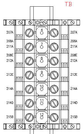
The terminal strip to edit, “TB”, is already placed on the drawing. Zoom in on terminal strip “TB” to see what the terminal strip currently looks like.
- Click

 . Find
- On the Terminal Strip Selection dialog box, select Terminal Strip “TB” and click Edit.
- On the Terminal Strip Editor dialog box, Terminal Strip tab, select terminal 1 in the grid.

- In the Terminal section, click the Move Terminal button.

- In the Move Terminal dialog box, click Pick Above. In the Terminal Strip Editor grid, select terminal 4.
Note: You can also use the Move Up tool to move terminal 1 to the top of the grid.
Click Done.
- Select terminal 4 in the grid.
- In the Properties section, click the Copy Terminal Block Properties button.

Notice that when you click Copy Terminal Block Properties, terminals 5 and 6 also highlight. It is because terminals 4, 5, and 6 are associated. If you copy the properties from one of these terminals, you also copy the properties from the associated terminals. The Copy Terminal Block Properties tool then copies the properties from the terminals to one or many terminals within the same terminal strip.
- Select terminal 7 and 10 in the grid by holding down the CTRL key while you select the terminals.
- In the Properties section, click the Paste Terminal Block Properties button.

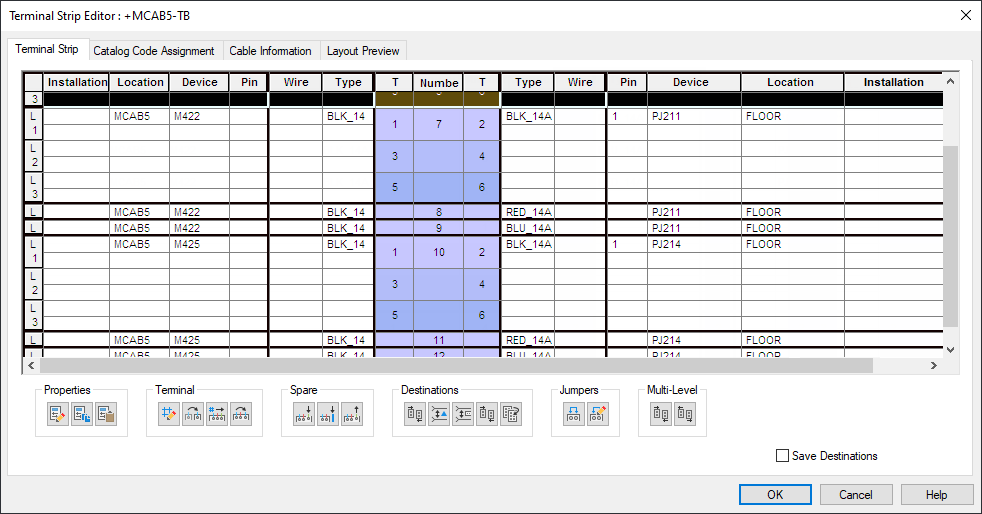
The properties you copied from terminal 4 are pasted to terminals 7 and 10. Notice that both terminals are now 3-tiered terminals with level 1 assigned for both.
Associate terminals
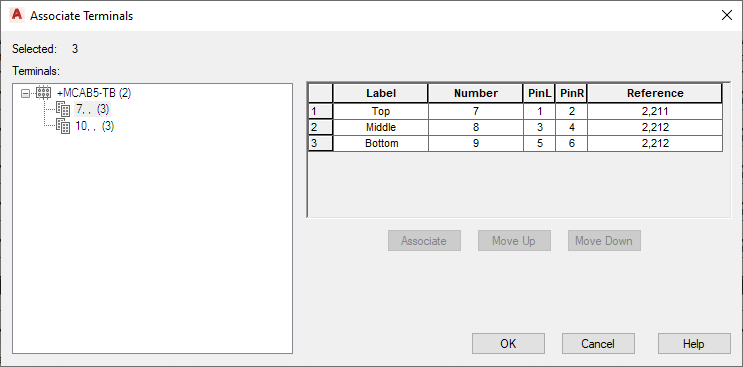
- Select terminals 8 and 9 in the grid.
- In the Multi-Level section, click the Associate Terminals button.

- On the Associate Terminals dialog box, select terminal 7, , (3) and click Associate.
Click OK.
- In the Spare section, click Delete Spare Terminals/Accessories to remove the blank terminals resulting from the Associate.

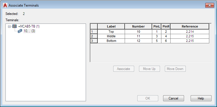
- On the Terminal Strip Editor dialog box, select terminals 11 and 12 in the grid.
- In the Multi-Level section, click the Associate Terminals button.

- On the Associate Terminals dialog box, select terminal 10, , (3) and click Associate.
Click OK.
- In the Spare section, click Delete Spare Terminals/Accessories to remove the blank terminals resulting from the Associate.

Insert spare terminals and accessories
- Select terminal 7 in the grid.
- In the Spare section, click the Insert Spare Terminal button.

- On the Insert Spare Terminal dialog box, specify:
Number: SPARE
Quantity: 1
Note: You can also assign catalog information for the spare terminal from the Insert Spare Terminal dialog box by clicking Catalog Lookup. If needed, you can then select the part from the Catalog Browser dialog box.Click Insert Above.
Now you insert accessories (end barriers) into the terminal strip - one at the top and one at the bottom of the terminal strip.
- Select terminal 1 in the grid.
- In the Spare section, click the Insert Accessory button.

- On the Insert Accessory dialog box, specify:
Number: EB1
Quantity: 1
Note: You can also assign catalog information for the accessory from the Insert Accessory dialog box by clicking Catalog Lookup. You can then select the part from the Catalog Browser dialog box.Click Insert Above.
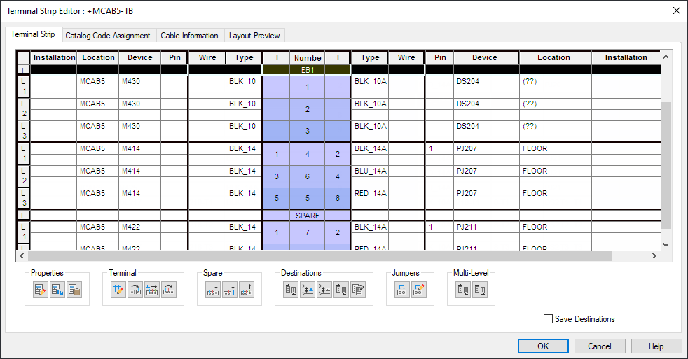
- Select terminal 15 in the grid.
- In the Spare section, click the Insert Accessory button.

- On the Insert Accessory dialog box, specify:
Number: EB2
Quantity: 1
Click Insert Below.
Insert the terminal strip into the drawing
- On the Terminal Strip Editor dialog box, click the Layout Preview tab.
- Select Graphical Terminal Strip as the terminal type to insert into the drawing.
- Enter 2.0 in Scale on Insert.
- Click Rebuild.
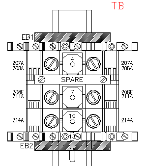
- On the Terminal Strip Editor dialog box, click OK.
- On the Terminal Strip Selection dialog box, click OK.