Select from a list of schematic components and place the panel footprints directly into a panel layout.
The footprint remains linked to the original schematic component, so you can perform bidirectional updating between schematic components and the associated footprint blocks.
Select schematic component footprints
- If AEGS is not the active project, in the Project Manager, right-click AEGS and select Activate.
- In the Project Manager, double-click AEGS to expand the drawing list.
- Open AEGS08.dwg.
- Click
 . Find
- In the Schematic Component List -- Panel Layout Insert dialog box, verify:
Extract component list for: Project
Location Codes to extract: All
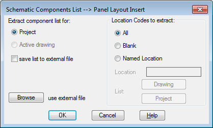
- Click OK.
- In the Select Drawings to Process dialog box, select AEGS04.dwg and click Process.
- Verify that AEGS04.dwg is listed in the Drawing to Process section and click OK.
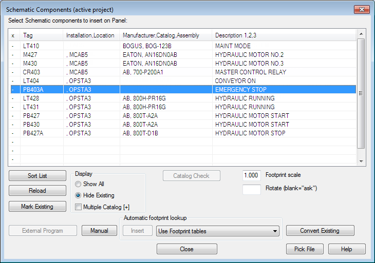
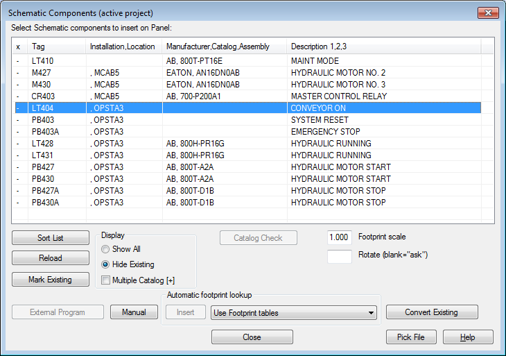
- In the Schematic Components (active project) dialog box, click Mark Existing. An
x marks the footprints that are already placed in the project.
You cannot insert the same component multiple times. If you select an item with an x, the Insert button is disabled.
Note: An o next to a component in the list indicates that a panel component with a matching component tag was found, but the catalog information does not match.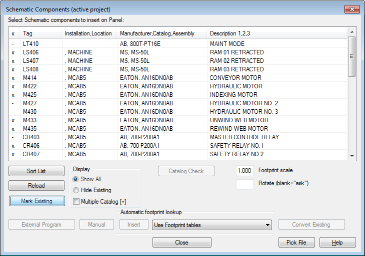
- In the Schematic Components (active project) dialog box, Display section, select Hide Existing.
The schematic component footprints not yet inserted into the panel layout are displayed.
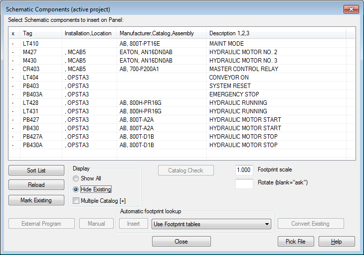
Now you can begin to insert schematic component footprints manually on the panel layout.
Insert the system reset footprint manually
- In the Schematics Components (active project) dialog box, select PB403 OPSTA3 SYSTEM RESET.
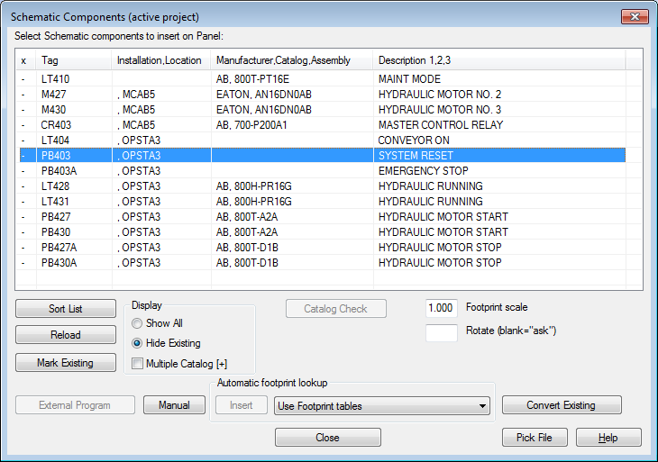
- Click Manual.
Note: The Manual button is used when schematic component footprints do not have a manufacturer and catalog number defined.
The next step is to make a catalog assignment for the automatic footprint.
- In the Footprint dialog box, Choice A section, click Catalog lookup.
Note: Use Choice B to enter a graphic without selecting a catalog number.
- On the Catalog Browser dialog box, enter the search string AB 800T.
- Click
 .
.
- Change the catalog assignment to 800T-A2A 1 NO 1 NC BLACK PUSH BUTTON - MOMENTARY, NEMA 4/13 and click OK.
- In the Footprint dialog box, Choice A section, verify:
Manufacturer: AB
Catalog: 800T-A2A
Click OK.
- Respond to the prompts as follows:
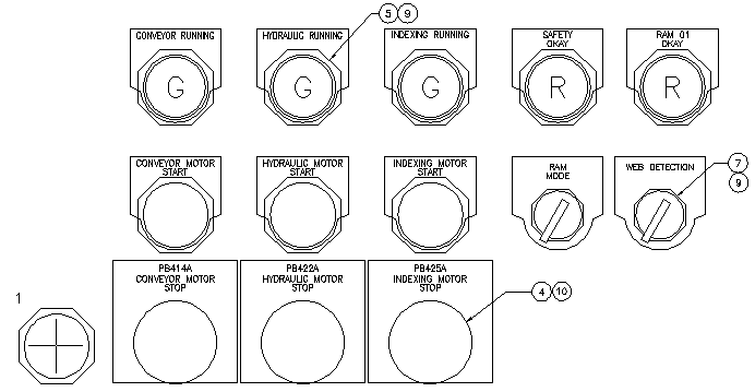
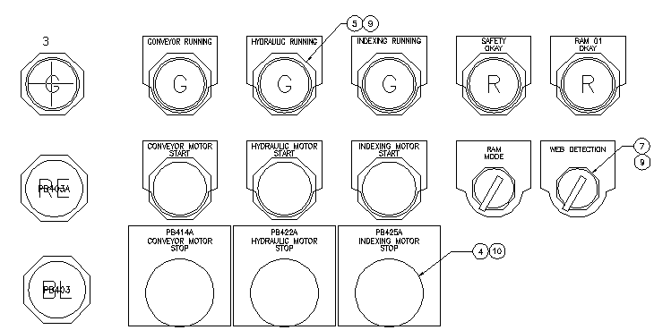
Select Location for PB403: Select to the left of PB414A (1)
Select Location for PB403: <Ortho on> select ROTATION:
Right-click to place the push button
The component may already have an Item Number assigned. If AutoCAD Electrical toolset finds a component with the same catalog information, it automatically assigns the same item number to this new component. If no item number is assigned, and you think a matching component exists, use one of the Find buttons to look through the drawing or project. If no matching component is found, click Next to assign an item number to this footprint. This button updates each time you insert a footprint and assign an item number. This item or detail number is used for BOM and component reporting and can be referenced by optional balloon labels tied to the footprint. If you do not want the item number to change if Resequence Item Numbers is run later on, check fixed next to the item number.
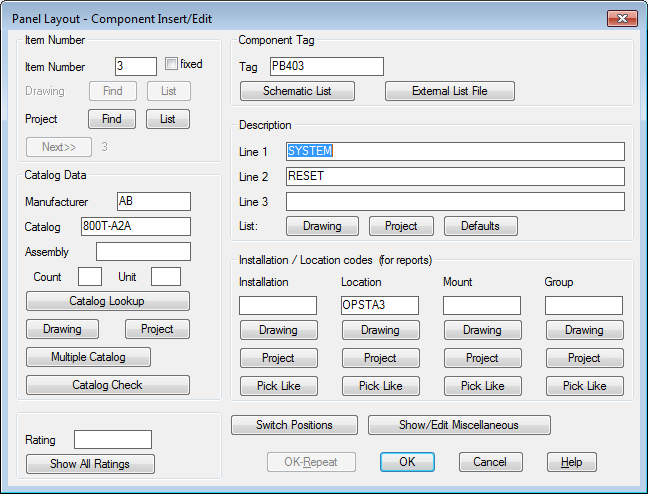 Note: The Panel Layout - Component Insert/Edit dialog box displays each time you insert a panel footprint. Information from the schematic representation is automatically carried over to the panel footprint representation.
 - In the Panel Layout - Component Insert/Edit dialog box, click OK.
The Schematics Component (active project) dialog box redisplays. You can continue inserting components from the schematic list of the project.
Insert the emergency stop footprint manually
- In the Schematic Components (active project) dialog box, select: PB403A OPSTA3 EMERGENCY STOP.
- Click Manual.
- In the Footprint dialog box, Choice A section, click Catalog lookup.
- On the Catalog Browser dialog box, enter the search string AB 30.5mm Red.
- Click
.
- Change the catalog assignment to 800T-D6A 1NO-1NC PUSH BUTTON-MUSHROOM, NEMA 4/13 and click OK.
- In the Footprint dialog box, Choice A section, verify:
Manufacturer: AB
Catalog: 800T-D6A
Click OK.
- Respond to the prompts as follows:
Select Location for PB403A: Select to the left of Conveyor Motor Start (2)
Select Location for PB403A: <Ortho on> select ROTATION:
Right-click to place the push button
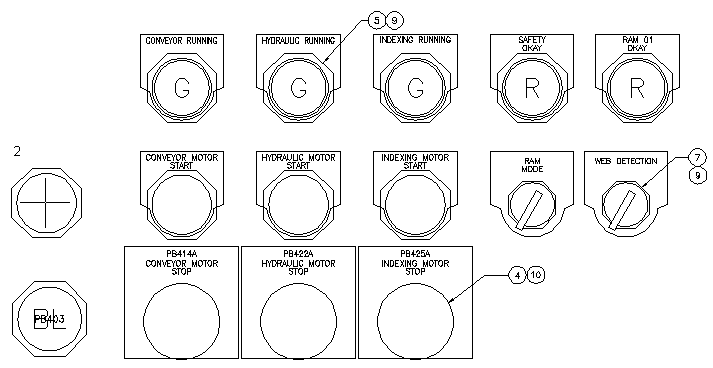
- In the Panel Layout - Component Insert/Edit dialog box, click OK.
Insert the light footprint manually
- In the Schematic Components (active project) dialog box, select LT404 OPTSTA3 CONVEYOR ON.
- Click Manual.
- In the Footprint dialog box, Choice A section, click Catalog lookup.
- On the Catalog Browser dialog box, enter the search string AB 30.5mm.
- Click
.
- Change the catalog assignment to 800H-QRT24G PLASTIC LENS 24VAC/VDC FULL VOLT GREEN PILOT and click OK.
Note: Click a column header to sort the catalog records based on the values in a specific field.
- In the Footprint dialog box, Choice A section, verify:
Manufacturer: AB
Catalog: 800H-QRT24G
Click OK.
- Respond to the prompts:
Select Location for LT404:
Select to the left of the Conveyor Running light (3)
Select Location for LT404: <Ortho on> select ROTATION:
Right-click to place the pilot light
- In the Panel Layout - Component Insert/Edit dialog box, click OK.
In the Schematics Components (active project) dialog box, notice the master control relay must still be placed.
- In the Schematic Components (active project) dialog box, click Close.
Note: You can modify a footprint at any time using the Edit Footprint tool. Since there is bidirectional update capabilities between the schematic and the panel layout drawings, it is possible to introduce some inconsistencies between the two during edit. AutoCAD Electrical toolset alerts you to check other drawings first, and then update any affected drawings.
- In the Update other drawings dialog box, click OK.
- If asked to save the drawing, click OK.