-
Click


 . Find
- Click the PLC Database File Editor tool.
- In the PLC Database File Editor dialog box, highlight PLCs in the PLC selection list and click New Module.
- In the New Module dialog box, specify the following:
- Manufacturer: Allen-Bradley
- Series: 1746
- Series Type: Discrete Input
- Code (Catalog Number): 1746-IA9
- Terminals: 9
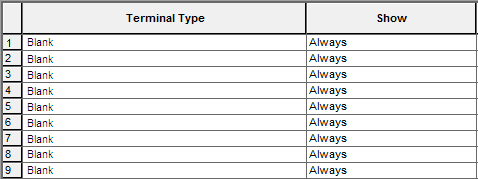
By default, when creating a PLC module the PLC Database File Editor lists as many blank field Terminal Types as there are terminals defined in the New Module dialog box.
- Addressable Points: 8
- Click OK.

You now have a new blank input module with nine terminals and eight addressable I/O points. You now need to define some information for each terminal in the module, the most important being what symbols AutoCAD Electrical toolset should stack together to build the module. Usually the top-most symbol for the module is a little different from the rest so that it can carry some basic information for the module that only needs to occur once in the final symbol.
Assigning Terminal Types
- In the PLC Database File Editor dialog box, right-click Terminal Type 1 and select Edit Terminal from the context menu.
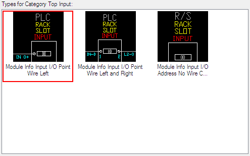
The Select Terminal Information dialog box appears. There are 3 categories for top symbols: Top Input, Top Output, and Top Terminal. Top Input and Top Output are addressable terminals, while the Top Terminal category consists of non-addressable terminals.
- In the Select Terminal Information dialog box, select Top Input.
The available terminals for that category appear along with any recently used terminals. Each terminal shown is slightly different. It may have an input wire connection terminal or have terminals for both input and output, or it may not have a wire connection.

- Select to use Module Info Input I/O Point Wire Left by selecting the picture and then click OK.
The selected terminal is assigned to the Terminal Type in the PLC Database File Editor dialog box. AutoCAD Electrical toolset looks at the block to see what attributes come in when the block is inserted. Some of the attributes come in with predefined values that can be overwritten. You will see these predefined values in the grid below the terminal type list.
- In the PLC Database File Editor dialog box, multiple-select the next seven terminals, right-click, and select Edit Terminal. Note: You can select multiple fields to edit at the same time by dragging your mouse across contiguous fields or by holding down the Control key while selecting non-contiguous fields.
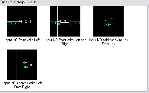
- In the Select Terminal Information dialog box, select the Input category and look at the available terminals.

- Select the Input I/O Point Wire Left terminal and click OK.
All seven terminals are assigned at the same time.

- In the PLC Database File Editor dialog box, right-click on the last terminal and select Edit Terminal.
- In the Select Terminal Information dialog box, select the Terminal category.
- Click the Terminal Point Wire Right terminal and click OK.
As an alternative to the Select Terminal Information dialog box, you can use the drop-down list of predetermined Terminal Types. Click the arrow for the Terminal Type and select from the list of available terminal types.
Setting additional terminal information
Some modules may have terminals that are not used. When you build your PLC module on an AutoCAD Electrical toolset drawing there is a choice inside the Module Layout dialog box to include unused/extra connections. When this toggle is not selected, all terminal entries marked as "Show: When Including Unused" in the PLC Database File Editor are skipped. When this toggle is selected, all entries marked with "Show: When Excluding Unused" are skipped. This gives flexibility to how a module is represented.
- In the PLC Database File Editor dialog box, make sure all of the terminals are set to Show: Always.
- Make sure all of the terminals are set to Optional Re-prompt: No.
You can trigger AutoCAD Electrical toolset to prompt for a new beginning address number when the parametric build flips from inputs to outputs or vice versa. On the line where you want AutoCAD Electrical toolset to re-prompt for a new output address, select Output. If you want a re-prompt for a new input address, select Input from the list.
- If you want a prompt for an automatic break in the PLC module, select the toggle in the Break After column.
- If you want to override the rung spacing for the I/O and wire connection point spacing, enter a value in the Spacing Factor column.
When AutoCAD Electrical toolset generates a PLC module, it uses the current rung spacing for I/O and wire connection point spacing. When a Spacing Factor is specified, AutoCAD Electrical toolset sees this spacing factor value on any terminal type I/O point or wire connection entry line, it uses a factor of the rung spacing. For example, a 2 for a given entry inserts this point down two times the rung spacing instead of a full rung spacing. A value of 1.5 inserts the point down an extra half rung spacing. A value of 0.0 puts the particular I/O point at the same location as the preceding one.
Modifying the terminal box dimensions
The Style Box Dimensions dialog box defines the module box dimensions (such as the offset values and line properties) based upon the style number used when the PLC was created.
- In the PLC Database File Editor dialog box, click Style Box Dimensions.
- Select Style 2 as the graphic style for your plc module. Styles 1-5 are predefined, styles 6-9 may be user-defined. Select a style number - a sample portion of a PLC module appears.
There are about two dozen symbols (with a file name "HP?*.dwg" where "?" is the style number) associated with each style in the library folder. To create a style, copy an existing style's symbols to one of the unused style numbers (6-9) and edit each library symbol.
Library folder: C:\Users\Public\Documents\Autodesk\Acade {version}\Libs\{library}\
- Specify the module box dimensions for the selected style.
These values set the right, left, top, and bottom offsets for the rectangle that surrounds the module. The optional Split Top and Split Bottom specify the offsets for a split module where Split Top specifies the offset for the top of a split module and Split Bottom specifies the offset for the bottom of the split module. If left blank, the rectangle Top and Bottom values are used.
- Specify any properties for the lines that make up the box. You can set the color and linetype using the properties fields. To predefine the color, enter "COLOR colorname" into the box. For linetype, enter "LTYPE linetypename" in the box.
- Click OK.
Modifying the terminal block settings
The Terminal Block Settings dialog box is used to manage the library symbols in the PLC Database File Editor. You can add a terminal to the list by clicking in any box in the last entry of the list. A blank entry line is added to the bottom of the list. You must define the block name, assign it to a terminal category for selection, give it a description, and assign a bitmap to be used for dialog box appears.
The list shows the block name, category, unique description, and sample bitmap file for each terminal type.
|
Block Name |
As defined when creating the parametric PLC blocks. Block file names adhere to the naming conventions to identify the PLC style numbering in the third position and the orientation in the first position. |
|
Category |
Used in the PLC Database File editor to easily find specific types of terminals. |
|
Unique Description |
These descriptions are used during the terminal type selection process. They need to be maintained as unique |
|
Sample Bitmap File |
This file is also used by the PLC database File editor to display a view of the terminal for selection. Symbols and BMP files need to be created outside of the PLC database file editor. Symbols are found in the standard library search path, while PLC Bitmap images are maintained in the same OS folder as the PLC Database itself, C:\Users\{username}\Documents\Acade {version}\AeData\{language code}\PLC |
- In the PLC Database File Editor dialog box, click Settings.
The Terminal Block Settings dialog box lists the library symbols for the terminal blocks that appeared in the Select Terminal Information dialog box. Notice that row 1 lists the block file name and sample bitmap file for the terminal we selected for Terminal Type 1.
- Switch between the various graphic styles. Notice that the block name updates depending on the style and orientation you select. For example, the block name is "HP1WA-DL" for Style 1, Horizontal. If you select Style 4, Vertical the block name changes to "VP4WA-DL".
Graphical styles are used during the operation of the PLC Parametric Selection process. These bitmap images appear during normal operation and selection of PLC entries and are found at C:\Program Files\Autodesk\AutoCAD {version}\Acade. Use the same file names that are already there: P_STYLEx.bmp where 'x' is the plc style 1-9.
- Click View DWG or View Bitmap to view the PLC parametric symbols.
- After you are done viewing the various symbols, click Cancel.
Adding terminal attributes
- Select the first terminal in the list of terminals.
The attributes associated to the block, along with any predefined values, appear below the Tree Structure section of the dialog box.

Notice that the value for the LINE1 is RACK %%1 and LINE2 is SLOT %%2. The prompting values of %%1 and %%2 are populated with what you type into the text box when prompted. The static text of Rack and Slot appears in the attribute once the PLC module is created. There are multiple prompting variables from %%1 through %%9. Prompting strings can be added to any existing attributes on the terminal block. If you wanted to add additional prompts with out using the existing attributes you would have to modify the block file to add additional attributes such as Line3.
Top terminals are the only symbols which can accept prompts during the parametric PLC insertion process.
- Edit each attribute value for the TAG attributes to read "IN-%%N."
Besides the Module Prompt variables, AutoCAD Electrical toolset also supports the use of an address variable. When the module is inserted, the PLC I/O addresses are calculated based on some AutoCAD Electrical toolset settings and the module settings. You can trigger AutoCAD Electrical toolset to include a prefix or suffix to each address value it inserts.
The %%N represents the calculated I/O address and the IN- is the prefix that gets added to the address value. You can also use the prompt values. For example, if you want to permanently encode the rack and group numbers (%%1 and %%2 prompts) into each I/O address value, encode each I/O address entry in the date file with "TAGA_=%%1%%2%%N."
- If you want to assign a text constant to any attribute value, combine a text constant with the variables as shown in the module prompts and addressing examples above.
Inserting the PLC module into the drawing
- Click Save Module to save the module to the PLC database file.
- Click Done/Insert.
The PLC Parametric Selection dialog box appears.
- Click OK to insert the new PLC module onto the drawing.
- Specify the insertion point on the drawing.
- In the Module Layout dialog box, click OK.
- In the I/O Address dialog box, specify a beginning I/O address or use the quick picks to select an address (such as I:/00).
- Click OK.
Your module should look like the following. The Manufacturer, Catalog Number, and Description attributes also display at the top of the module (not shown).
