There are three ways to predefine attribute values for a component.
- On the marker block for the component in the circuit template drawing.
- In the Circuit Builder spreadsheet circuit codes sheet.
- Annotation presets - provides the ability to select which attribute values to apply when the circuit is inserted.
Marker block method
- Open the circuit template drawing that contains the marker block for the component.
- Find the correct marker block for the component.
- Edit its MISC1 attribute value using the format “{attribute name}={attribute value}”, for example, “DESC1=MOTOR”.
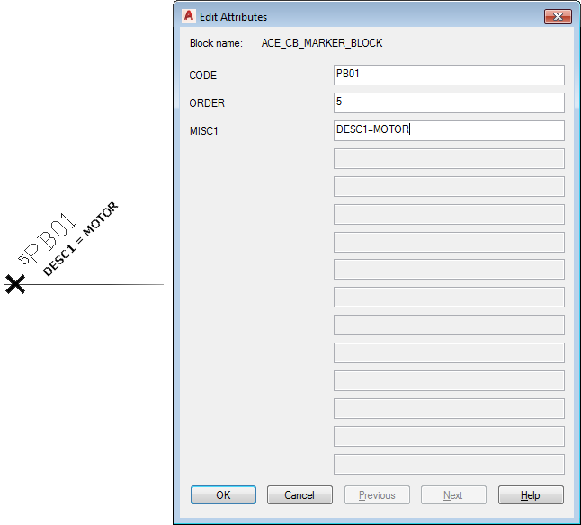 Note: The MISC1 attribute value can contain multiple special text flags which direct Circuit Builder to handle the component or underlying wire in a special way. When you add new values, do not overwrite any other special flag values. Separate each one with a semicolon.
 - Save the circuit template drawing.
Spreadsheet method
- Open the Circuit Builder spreadsheet, ace_circuit_builder.xls.
- Find the circuit CATEGORY and TYPE, for example CATEGORY: 3ph Motor Circuit and TYPE: Horizontal - FVNR - non reversing.
- Open the circuit code sheet with the same name as the SHEET_NAME value, for example SHEET_NAME: 3ph_H.
- Find the specific component, for example CODE: PB01, COMMENTS: STOP, UI_PROMPT_LIST: Push button - Standard.
There can be multiple selections within the group. For example, there is a selection for the type of disconnecting means, and a selection to include an auxiliary contact. Each selection is assigned a numerical value from the UI_VAL field. The values are added to determine the appropriate action for this combination of selections. The sum is matched to a value in the UI_SEL field. Once this match is made, the COMMAND_LIST value, ANNOTATE_LIST value, and so on, are used to insert and annotate the selections.
- Edit the API call in the COMMAND_LIST column for this component. For example, the last argument of this Insert Component API call is used to predefine MISC1 coded values with nil when nothing extra is defined.
Before and after are shown:
Before: (c:ace_cb_insym #xyz nil "HPB12" #scl 8 nil)
After: (c:ace_cb_insym #xyz nil "HPB12" #scl 8 “DESC1=CONVEYOR;DESC2=SYSTEM RESET”)
Note: See the API documentation for more information. - Save the spreadsheet.
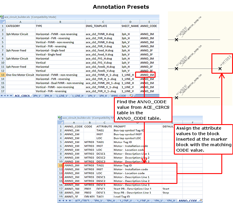
Annotation Presets
Annotation presets allow you to:
- Predefine description text, installation, location values for individual components in the circuit.
- Select which attribute values to apply to the circuit when it is built.
- Edit the attribute values before the circuit is built.
- Open the Circuit Builder spreadsheet, ace_circuit_builder.xls.
- Open the ACE_CIRCS sheet.
- Find the circuit CATEGORY and TYPE, for example CATEGORY: 3ph Motor Circuit and TYPE: Horizontal - FVNR - non reversing.
- Assign a code value in the ANNO_CODE field if there isn’t one, for example ANNO_3M.
- In AutoCAD Electrical toolset, open the circuit template drawing listed in the DWG_TEMPLATE field, for example ace_cb1_FVNR_H.dwg.
- Open the ANNO_CODE sheet in the spreadsheet.
This sheet provides a link between the circuit you select (identified by the ANNO_CODE value), a specific marker block (identified by its CODE value), and a specific attribute on the marker block.
- Enter the ANNO_CODE value from earlier in the ANNO_CODE field of a blank row, ANNO_3M.
For this example, you define some attribute values for the motor symbol.
- In AutoCAD Electrical toolset, find the marker block that defines the insertion point for the motor symbol. Find the CODE attribute value, for example MTR03.
- In the spreadsheet, add a new line in the ANNO_CODE table for each attribute you wish to predefine. For example:
- ANNO_CODE = ANNO_3M. It is the value from the ACE_CIRCS sheet for this circuit.
- CODE = MTR03. It is the value from the CODE attribute on the marker block.
- ATTRIBUTE = LOC. It is the attribute name you want to predefine.
- PROMPT = Motor - Location code. This is the text used on the Annotation Presets dialog box. This dialog box is displayed if you select the Presets - List button when the circuit is inserted.
- Default = FIELD. It is the attribute value to apply to the LOC attribute when the motor symbol is inserted.
- Repeat for each attribute value you want to predefine. The ANNO_CODE and CODE values should be the same for each attribute on this motor symbol.
- Save and close the spreadsheet.
You are now ready to test the changes.
-
Click
 . Find
- Select the circuit CATEGORY and TYPE, CATEGORY: 3ph Motor Circuit and TYPE: Horizontal - FVNR - non reversing.
- Select the Presets button in the Special Annotation section.
- Select the Lists button next to Presets.
The Annotation Presets dialog box displays. Any attributes with non-blank values are selected by default and applied to the symbol when it is inserted. You can select which attribute values to apply or edit the values as necessary.
- Select OK.
- On the Circuit Selection dialog box, select Insert.
The circuit is built and the attribute values are applied.