Specify the wire parameters and select a wire size from a list of wire sizes that meet or exceed the parameters. Estimated energy losses per wire size can provide valuable information in this selection.
Find Command entry:
AECIRCBUILDER
Command entry:
AECIRCBUILDER
On the Select Circuit dialog box, select a circuit, click Configure, enter the Motor Setup parameters, and then select the Wire Setup Browse button.
Load
|
Voltage |
Sets the voltage for the wire conductor. |
|
Phase |
Sets the phase of the electrical power. |
|
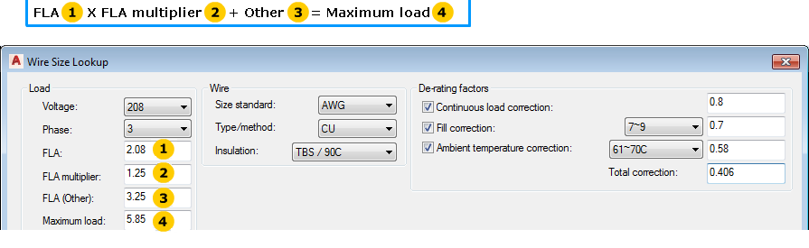
FLA |
Sets the full load amps carried by the wire conductors. |
|
FLA multiplier |
Sets the value that is multiplied by the FLA value to calculate the maximum load for the wire conductors. |
|
Other |
Sets the amp value of any additional loads to be combined with the main motor or load and fed from this common branch circuit set of conductors. This value is added to the product of the FLA times FLA multiplier. |
|
Maximum load |
Displays the calculated maximum load for the conductors. It is based on the FLA (Other) value added to the product of the FLA times the FLA multiplier value. |
Wire
|
Size standard |
Sets the wire standard. Directs Circuit Builder to use specific tables from the electrical standards database for that wire size standard. The available values are extracted from the electrical standards database table names. |
|
Type/method |
Sets the wire metal type. Directs Circuit Builder to use specific tables from the electrical standards database for that wire metal type. The available values are extracted from the electrical standards database table names. |
|
Insulation |
Sets the wire insulation and temperature rating type. The available values are extracted from the electrical standards database file. |
De-rating factors
|
Continuous load correction |
Specifies whether to include a continuous load de-rating factor in the calculation of the wire ampacity. For example, continuous equals three hours or longer. When Continuous load correction is on, sets the de-rating factor. This value is used in the total de-rating factor used to calculate wire ampacity. |
|
Fill correction |
Specifies whether to include a fill correction de-rating factor in the calculation of the wire ampacity. When Fill correction is on, sets the range of current carrying conductors that are grouped in a common conduit, raceway, or cable. When Fill correction is on, sets the de-rating factor for the selected fill range. This value is used in the total de-rating factor used to calculate wire ampacity. |
|
Ambient temperature correction |
Specifies whether to use a de-rating factor for an elevated ambient temperature. When Ambient temperature correction is on, sets the range of maximum ambient temperature. When Ambient temperature correction is on, sets the correction factor value. This value is used in the total de-rating factor used to calculate wire ampacity. |
|
Total correction |
Displays the calculated total correction factor based on the individual de-rating settings. You can manually set the total de-rating value. The value is multiplied with the defined ampacity to calculate the actual de-rated ampacity of the wire. |
Parameters
|
Run distance |
Specifies whether to consider the length of the wire run in calculation of the voltage drop. When Run distance is on, sets the distance. |
|
Units |
When Run distance is on, sets the distance units. |
|
Via |
When Run distance is on, sets the type of conduit or raceway which affects the voltage drop calculation. The available types are extracted from the electrical standards database file. |
|
Power factor |
When Run distance is on, sets the power factor value used to calculate the voltage drop. |
|
Maximum % voltage drop |
Specifies whether to apply a maximum percent voltage drop limit on what size wires are appropriate. When Maximum voltage drop is on, sets the acceptable maximum percentage of voltage drop along the wire length. |
Paralleled wires
|
Include paralleled wire options |
Specifies whether to include paralleled wire options in the display. When on, the display includes entries consisting of two or more smaller size conductors per phase to meet the ampacity requirement of the load. |
|
Maximum paralleled wire count |
When Include paralleled wire options is on, sets the maximum conductors per phase to use in the calculation and display. |
|
Minimum paralleled wire size |
When Include paralleled wire options is on, sets the minimum wire size to use for paralleled conductor calculations. |
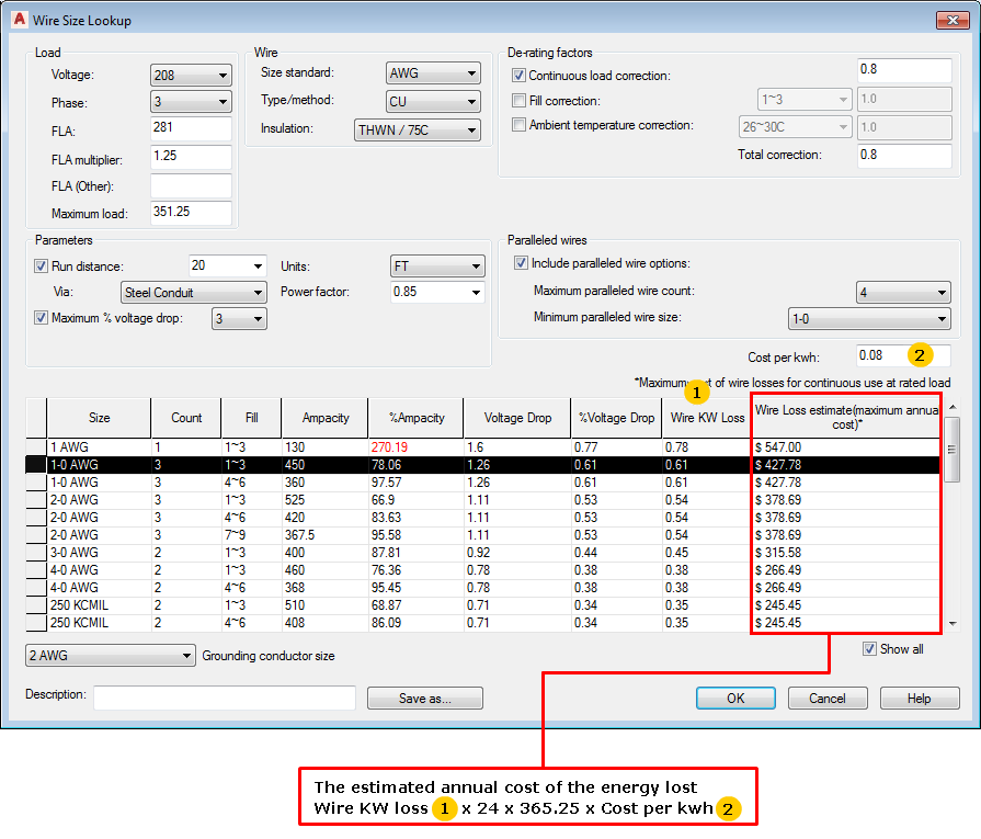
Cost per kwh
Sets the cost per kilowatt hour used in the wire loss calculations.
Wire grid
Displays the available wire conductors, extracted from the electrical standards database, for selection. Wires that do not meet the ampacity requirements are shown in red.
|
Size |
Wire sizes extracted from the wire ampacity table in the electrical standards database. |
|
Count |
When Include Paralleled Wire options is on, indicates the number of conductors per phase. |
|
Fill |
When Include Paralleled Wire options is on, indicates the fill calculation which takes into account the fill correction.
Note: This value is displayed regardless of the state of the Fill correction check box when the Include Paralleled Wire options is on.
|
|
Ampacity |
Calculated ampacity for the conductor. It is the ampacity, extracted from the wire ampacity table, multiplied by the total correction de-rating factor. |
|
%Ampacity |
The Maximum load value divided by the Ampacity. It indicates if the wire is close to being fully loaded. |
|
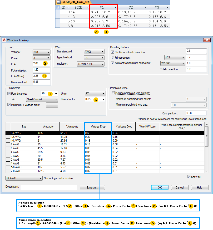
Voltage Drop |
The calculated voltage drop from one end of the power run to the other. It can only be calculated if the conductor length is defined. |
|
%Voltage Drop |
The Voltage Drop value divided by the applied voltage and multiplied by 100. |
|
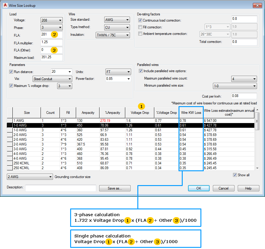
Wire KW Loss |
Calculated from the Voltage Drop and FLA. |
|
Wire Loss estimate (maximum annual cost) |
Maximum cost of wire losses for continuous use at rated load. |
|
Show all |
Specifies whether to display entries where the %Ampacity value is greater than 100%. When Show all is on, values that are greater than 100% are shown in red. Entries >= 300% ampacity are never shown in the list. |
Grounding conductor size
Displays the minimum size grounding conductor based on the FLA of the motor or power feed. Select a larger conductor size from the list.
The suggested wire conductor size is determined from the appropriate AMPG* table in the electrical standards database file.
Save as
|
Save as |
Saves the current settings, wire options, and identifying values from the Select Motor dialog box as an external file. |
|
Description |
Assigns a description for the parameters and wire options. Uses this description when you select Save as to save the current settings and wire options as an external file. |