AutoCAD provides many tools for quick and accurate measurements of distances, areas, lengths, angles, and other geometric calculations. Obtaining measurements is a fundamental aspect when creating and transforming your drawings to real-world objects or structures.
Let's say following the amendments to your county guidelines, your company has determined the current configurations of the rooms don't adhere to the building standards. In this article, we'll calculate the room area and use that as the basis in identifying the maximum number of occupants allowed in a meeting room.
Getting Started
The purpose of the following steps is to create a simple room layout using metric units.
- Start a new drawing from a metric template. For this exercise, we'll use
acadiso.dwt.
For more information about templates, see Have You Tried: Working with Templates.
- Define the drawing units by clicking the Application button

 Drawing UtilitiesUnits.
Find
Drawing UtilitiesUnits.
Find
- In the Drawing Units dialog box, specify the following and click OK.
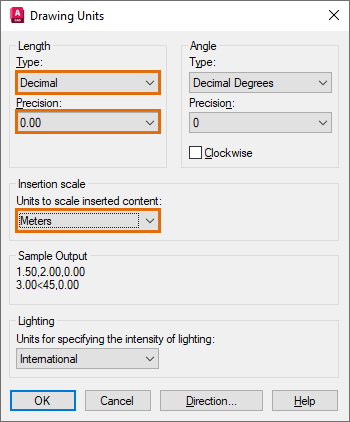
Measurements in the current drawing are displayed in decimal format and one drawing unit represents one meter.
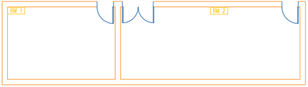
- Create some geometry as shown. You can draw polylines or use the RECTANG command to create a rectangle.
- Save the drawing.
Calculate and Display the Area
The following steps explain how to calculate the room areas so that we can determine the maximum number of occupants allowed in a room.
There are several ways to find the area information of an object or using specified points. You can use the Properties palette or use commands such as AREA, MEASUREGEOM, or LIST.
- If the Properties palette is not displayed, select any object. For example, the perimeter of RM 1 as shown.
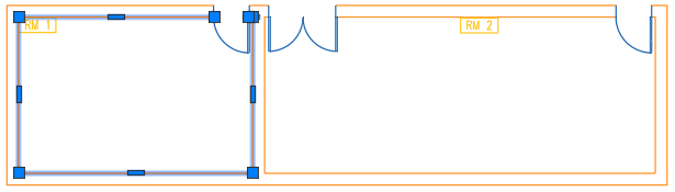
- Right-click and choose Properties.

Properties of the selected object, including the area, are displayed.
Note: Unlike individual lines, polylines are considered closed objects and always have a calculated area. - Calculate the area of RM 2 using a series of points. On the ribbon, click Home tabUtilities panelMeasure drop-downArea.
Find
Or at the Command prompt, type aa (AREA).
- Specify the points in a sequence that outlines the perimeter of the RM 2. You don't need to duplicate the first and last points.
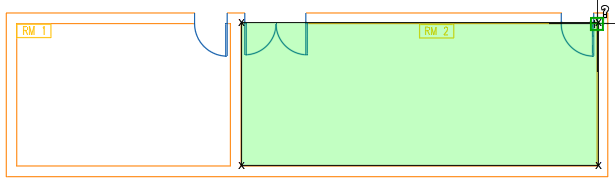
The enclosed perimeter highlighted in green defines the area to be calculated.
- Press Enter. Make sure that the Area option is selected.
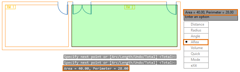
The calculated area is displayed in the command window and in a dynamic tooltip. If the results aren't visible, press F2 to open the command window.
- On the ribbon, click Home tabUtilities panelMeasure drop-downQuick.
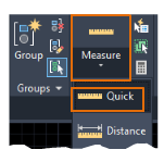
You can see calculated values as you move your mouse over and between objects.
- Hover to a space inside the perimeter of RM2.
- Click when the sides of the perimeter are highlighted.
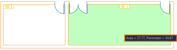 Note: The Quick option is designed to dynamically display the calculated area of an enclosed object. Notice that the defined area, highlighted in green, excludes the open spaces. Shift+click to specify multiple enclosed areas to calculate.
Label the Calculated Area
Let's insert some labels that display the area of the meeting rooms. While the AREA or MEASUREGEOM commands or Properties palette show the room area, these don't create a label in your drawing. We'll use multileader objects (MLEADER) and fields to display the area. For information and tips on using MLEADER, see Have You Tried: Multileaders for Labels and Callouts.
- Click the Annotate tab and locate the Leaders panel. Click the Multileader tool.
- Click anywhere inside the perimeter to specify the arrowhead location and then click a location for the leader landing.
- Type your text content (for example, "Area=").
- Place the cursor where you want the field text to appear. Right-click and choose Insert Field.
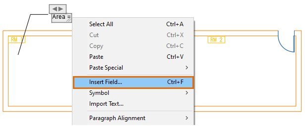 Tip: Press Ctrl+F if the Insert Field option is not visible in the shortcut menu.
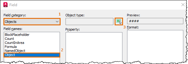
 - In the Field dialog box, specify the options in order as indicated.
The Field dialog box closes temporarily.
- In the drawing window, select the polyline that defines the perimeter of RM 1. The Field dialog box redisplays.
- The available properties for the selected object are displayed. Under Property, select Area.
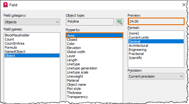
A preview of the calculated value of the selected property is also displayed.
- Click OK.
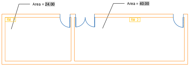
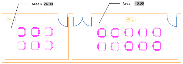
The area for the selected room is displayed in the text of the multileader object.
- On the Text Editor ribbon contextual tabClose panel, click Close Text Editor. Alternatively, click in the drawing outside the in-place text editor.
- Repeat the steps to create a label for the area of RM 2.
The perimeter of RM 2 is outlined with an open polyline. When prompted to select the object in the Field dialog box, click the polyline that makes the bottom and sides of the room. The top line isn't a closed polyline for the room. A good practice is to check the preview of the calculated value in the Field dialog box.
 Tip: The data in the field doesn't update automatically. The FIELDEVAL system variable controls when fields are recalculated. If set to the default value, a save or a REGEN will update the field. Alternatively, double-click the text of the multileader object (where the field is inserted). Right-click and choose Update Field.
| Meeting Room | Area (m2) | Maximum Occupants |
|---|---|---|
| RM 1 | 24.00 | 6 |
| RM 2 | 40.00 | 10 |
Arrange and Space Out the Objects
Let's add some furniture in the meeting rooms and arrange the chairs so that they're at least a meter apart.
- Click View tabPalettes panelDesignCenter.
Find
- In the DesignCenter tree view, navigate to the content you want to add to the drawing. For this example, "CHAIR7" is located in the %ProgramFiles%\Autodesk\AutoCAD <release>\Sample\Database Connectivity\Floor Plan Sample.dwg\Blocks folder.
- Insert six chairs in RM 1 and 10 chairs in RM 2, respectively.
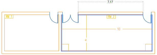
- Check the distance between the chairs. Click Home tabUtilities panelMeasure drop-downQuick.
The Quick option is particularly useful in displaying real-time distances within a drawing. You can also use the DIST command to find the distance between specified points.
- As you move your cursor, distances between the objects are shown dynamically.
- Rearrange and properly space the objects.
Summary
Accurate measurements in the drawing can save time and cost, and verify the feasibility of your designs.