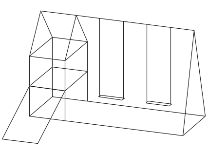
A 3D wireframe model is an edge or skeletal representation of a real-world object.
3D wireframe models consist of points, lines, arcs, circle, and other curves that define the edges or center lines of objects.

You can use a 3D wireframe model to
- Generate basic 3D designs for evaluation and fast design iterations
- View the model from any viewpoint
- Analyze spatial relationships, including the distances between corners and edges, and checking visually for potential interferences
- Generate perspective views (not available in AutoCAD LT)
- Generate standard orthographic and auxiliary views automatically
- Act as reference geometry for 3D solid, surface, and mesh modeling
It's strongly recommended that you keep 3D wireframe geometry on a separate reference layer for convenient access when checking the integrity of a 3D model or for recreating portions of it.
Methods for Creating 3D Wireframe Models
Wireframe modeling requires practice and experience. The best way to learn how to create wireframe models is to begin with simple models before attempting models that are more complex.
You can create wireframe models by positioning any 2D planar object anywhere in 3D space, using the following methods:
- Enter 3D coordinates that define the X, Y, and Z locations of the defining points of an object.
- Set the default work plane, which is the XY plane of the UCS, on which to create planar objects such as an arcs or circles.
- Move, copy, or rotate the object to its 3D location after you create it.
Example of a 3D Wireframe Model

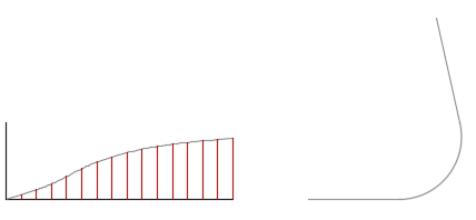
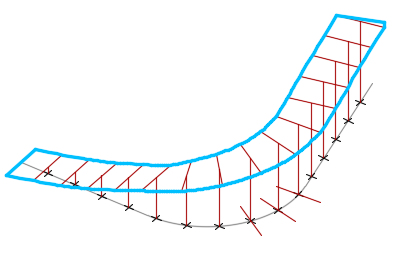
The equally spaced, T-shaped construction lines provide points for an inner and outer B-spline edge for the road. The tops of each T can be canted or crowned.

From here, the splines can be used to create a 3D solid for rendering, for cut and fill calculations, or for structural engineering calculations.
Tips for Working with 3D Wireframe Models
Creating 3D wireframe models is more challenging than creating 2D orthographic views. Here are some tips that will help you work more effectively:
- Use multiple views, especially isometric views, to make visualizing the model and selecting objects easier, and to avoid mistakes.
- Plan and organize your model so that you can turn off layers to reduce the visual complexity of the model. Color can help you differentiate between objects in various views.
- Create construction geometry to define the basic envelope of the model before adding detail.
- Become adept at manipulating the UCS in 3D. The XY plane of the current UCS operates as a work plane to orient planar objects such as circles and arcs. The UCS also determines the plane of operation for trimming and extending, and offsetting objects. The Z axis of the UCS determines the axis direction for rotating objects about a point.
- Use object snaps carefully to ensure the precision of your model. Once made, mistakes can easily proliferate through your model.
- Use coordinate filters to drop perpendiculars and locate points in 3D based on the location of points on other objects.