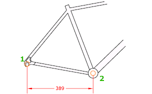
Creates a linear dimension.
Access Methods
Tool Set:
.

Menu: .
Summary
Creates a linear dimension with a horizontal, vertical, or rotated dimension line. This command replaces the DIMHORIZONTAL and DIMVERTICAL commands.

List of Prompts
The following prompts are displayed.
Specify first extension line origin or <select object>: Specify a point or press Enter to select an object to dimension
After you specify the extension line origin points or the object to dimension, the following prompt is displayed:
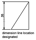
Specify dimension line location or [Mtext/Text/Angle/Horizontal/Vertical/Rotated]: Specify a point or enter an option
First Extension Line Origin
Prompts for the origin point of the second extension line after you specify the origin point of the first.

Dimension Line Location
Uses the point you specify to locate the dimension line and determines the direction to draw the extension lines. After you specify the location, the dimension is drawn.

Mtext
Displays the In-Place Text Editor, which you can use to edit the dimension text. Use control codes and Unicode character strings to enter special characters or symbols.
If alternate units are not turned on in the dimension style, you can display them by entering square brackets ([ ]).
The current dimension style determines the appearance of the generated measurements.
Text
Customizes the dimension text at the Command prompt. The generated dimension measurement is displayed within angle brackets.
To include the generated measurement, use angle brackets (< >) to represent the generated measurement. If alternate units are not turned on in the dimension style, you can display alternate units by entering square brackets ([ ]).
Dimension text properties are set on the Text tab of the New, Modify, and Override Dimension Style dialog boxes.
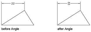
Angle
Changes the angle of the dimension text.

Horizontal
Creates horizontal linear dimensions.

- Dimension Line Location
-
Uses the point you specify to locate the dimension line.
Vertical
Creates vertical linear dimensions.

- Dimension Line Location
-
Uses the point you specify to locate the dimension line.
Rotated
Creates rotated linear dimensions.

Object Selection
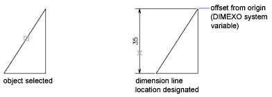
Automatically determines the origin points of the first and second extension lines after you select an object.
For polylines and other explodable objects, only the individual line and arc segments are dimensioned. You cannot select objects in a non-uniformly scaled block reference.
If you select a line or an arc, the line or arc endpoints are used as the origins of the extension lines. The extension lines are offset from the endpoints by the distance you specify in Offset from Origin in the Lines and Arrows tab of the New, Modify, and Override Dimension Style dialog boxes. See DIMSTYLE. This value is stored in the DIMEXO system variable.

If you select a circle, the diameter endpoints are used as the origins of the extension line. When the point used to select the circle is close to the north or south quadrant point, a horizontal dimension is drawn. When the point used to select the circle is close to the east or west quadrant point, a vertical dimension is drawn.