All AutoCAD MEP 2022 toolset objects have one or more smart connectors (connection points). These smart connectors enable objects to connect intelligently to appropriate objects and to transfer information such as shape, size, and system. You add connectors to style-based objects such as plumbing fittings by adding the connectors to the styles that define the objects. You can also remove connectors from styles, or change their type and location.
Because plumbing fittings have grips, it is important for the connectors of a plumbing fitting style to be configured correctly. For a given connector, the connection point value must be the length of the segment, and its connection direction must be positive (1) or negative (-1) depending on its orientation from the origin (0,0). In addition, you must define the connectors in a specific order. The following image of an elbow, tee, and cross identifies the order for each type of fitting.
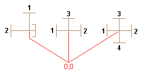
For example, the following table identifies how you would configure an elbow, tee, and cross—all with segments 0.5 inches long.
| Part Type | X, Y, and Z Values for Connection Direction | X, Y, and Z Values for Connection Direction |
|---|---|---|
| Elbow |
|
|
| Tee |
|
|
| Cross |
|
|