Use this procedure to add connectors to a block-based MvPart. Defining connectors allows the part size to be connected intelligently to other building systems objects in a drawing. You can define one or more connectors for each part size of an MvPart. You can assign each connector unique part properties, such as domain, system type, shape, and size. Generally, a part has at least one connector. However, you can create a part that has no connectors. For more information, see Connectors of a Block-Based Part.
- To add a connector, from the tree view of the part family and sizes, right-click the part family, and select the type of connector.
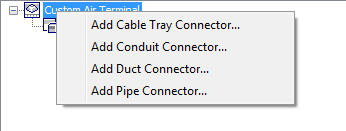
Shows example of context menu for part family
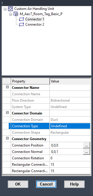
The Part Family Connector Properties dialog box is displayed.

Part Family Connector Properties dialog box
- Specify a value for each of the properties and click OK:
To specify the… then click the value cell and… Name enter a descriptive name. Connection Shape select a shape from the list. The available shapes are dependent on the domain of the connector. additional properties, such as Flow Direction select from the list. Additional properties that are available are dependent on the domain of the connector. Unsized select True or False. Selecting True allows the connector to be unsized and valid connections to be made with unsized segments. These properties are assigned to the connector for all part sizes.
Note: The connector domain is based on the type of connector selected and cannot be changed in the properties dialog box. Also, the Unsized value cannot be changed once the connector is defined. - To edit connector properties, right-click a connector, and click Edit Placement.
A property palette is displayed.
Example of connector property palette
- Specify the connector properties:
To specify the… then… position of the connector enter p (position), or click  for Connection Position, and select a point on the model. The connection position is updated in the palette. If you added object point to the model at the locations of the connectors, use the Node object snap to snap to the location.
 direction to draw connecting components by a single point enter n (normal), or click for Connection Normal, drag the cursor in the correct direction, and select a point. The connection normal is updated in the palette. To ensure that components are connected perpendicularly to the part, use AutoCAD’s Ortho mode to restrict the cursor when selecting the direction. direction to draw connecting components by 2 points enter n (normal), select the first point, and then select the second point. The connection normal is updated in the palette. type of connection in the property palette, select a type for Connection Type. rotation of the connector in the property palette, enter a number of degrees for Rotation. Typically, the rotation value is 0 (zero). size of the connector in the property palette, enter a number for the size properties. The size properties vary depending on the shape of the connector. - Click OK, and then click Next.