You construct a model bit by bit, building shapes to add to it and using tools to cut away the portions of the shapes you do not need. In Content Builder, these shapes are features of the part you are creating. Geometry features are the basic building blocks for defining the size and shape of the model.
Geometry that you define is 2-dimensional (2D) and must be attached to a work plane. You can switch between work planes to define different geometry. As you add geometry to a work plane, the geometry features appear under the Geometry folder of the associated work plane.
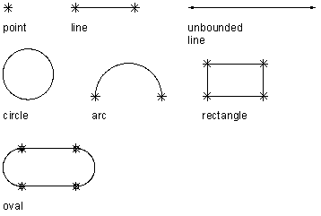
Viewing geometry types
Content Builder provides 9 types of geometry you can use to build the model:
- Point
-
Defined by an X and Y coordinate.
- Line
-
Defined by a position and a direction; constrained by a start point and endpoint.
- Unbounded Line
-
Defined by a position and a direction; infinite in length because it has no constraining start point or endpoint.
- Circle
-
Defined by a center point and a radius.
- Arc
-
Defined by a center point and a radius; constrained by a start point and endpoint.
- Rectangle
-
Defined by lines and points that are constrained to maintain start points and endpoints for each side and perpendicular angle.
- Oval
-
Defined by lines, arc, and points that are constrained to create 2 arcs tangent to 2 lines, with defined start points and endpoints.
- Point Reference
-
Defined by a point in the work plane that is based on a source point selected from a different work plane. A point reference is moved or deleted with the source point.
- Project Geometry
-
Defined by a projection of a modifier on a specified work plane. The project geometry is fixed and cannot be moved in the work plane. It is linked to the modifier and adjusts as the modifier changes.