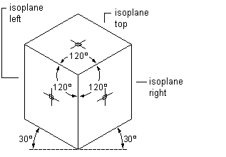
You can draw a schematic diagram in isometric mode. Isometric mode simulates a 3-dimensional (3D) plan view, where lines are drafted on rotated isoplanes and symbols appear tilted along the isometric axes. This provides the illusion of a 3D view in a 2D model.
Isometric drawings simulate a 3D object from a particular viewpoint by aligning along 3 major axes. The Isoplane option on the Properties palette restricts cursor movement to appropriate rotated angles along isometric planes. You can work on one of 3 isometric planes, each with an associated pair of axes:
- Left. Aligns symbols and lines along 90-degree and 150-degree axes.
- Top. Aligns symbols and lines along 30-degree and 150-degree axes.
- Right. Aligns symbols and lines along 30-degree and 90-degree axes.

Viewing isometric planes
Choosing one of the 3 isometric planes causes the AutoCAD® Ortho mode and the crosshairs to be aligned along the corresponding isometric axes in the WCS. You can switch between planes as you draft. For example, you can start a run on the top plane, switch to the left plane to draw a riser, and then switch to the right plane to complete the run.
Although an isometric drawing appears to be 3D, it is actually a 2D representation. Therefore, you cannot extract 3D distances, display objects from different view ports, or remove hidden lines automatically.