Use this procedure to add connectors to the model. The shape of the connector is determined by the shape of the modifier selected. After the connector has been placed, you can assign the connector type.
The Content Builder requires a minimum of 3 connectors to create a usable tee fitting. To ensure the fitting can be added in a drawing with valid connections, the connectors must be added in a specific order. In plan view, add connectors left to right, then bottom to top. The following example shows connectors placed on a tee fitting.
Placing connectors on a tee fitting
- To add a connector, in the part browser, right-click Connections and click Add Connection.
The software prompts you to select the connector location. As you move the cursor around in the modeling area, it snaps to 4 possible locations for a connector—to both ends of the trunk and both ends of the branch.
- To specify the first connection point, select the connector location on the left end of the trunk.
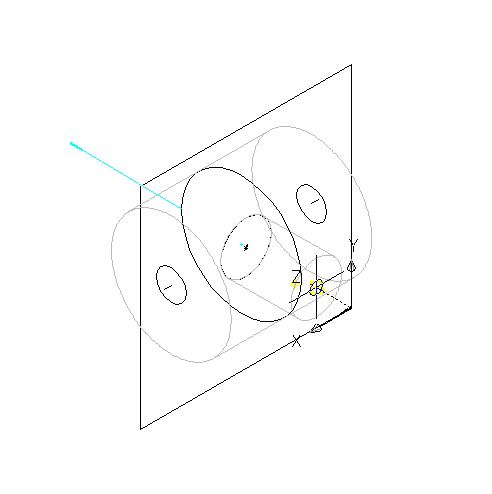
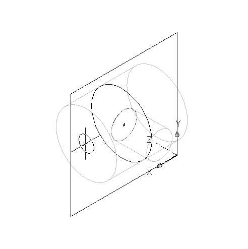 Attention: The position of the first connector placed in the model defines the axis orientation of the part upon insertion. For example, if you place the first connector on a part with a perpendicular vector into the part, the direction of the vector defines the positive x-axis orientation when inserted into a drawing.
 - Press Enter to accept the default value for the first connector number. Tip: The default connector numbers are in ascending numeric order, according to the order in which the connectors are added to the model. For example, the first connector is 1, the second connector is 2, and so on. You can model connections in any order you choose. However, specific parts require specific connections set in a known order. The order given for this example is valid for all tees and other fittings.
- Select a location to the left of the model to place the dimension for the profile of the trunk.
A diameter dimension (D1) is added to the model for the circular profile of the trunk. The D1 dimension is also added to Size Parameters in the part browser, and a connector is added to Connections.
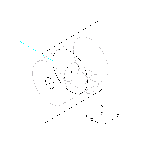
- To specify the second connection point, right-click Connections in the part browser, click Add Connection, and select the connector location on the right end of the trunk.
- Press Enter to accept the default value for the second connector number.
You do not need to select a location for the dimension because the same profile is used for both ends of the trunk. However, the software does add a diameter dimension (D2) defined with the value of D1 to Model Parameters in the part browser. The software also adds a diameter dimension (D2) to Size Parameters and a second connector to Connections.
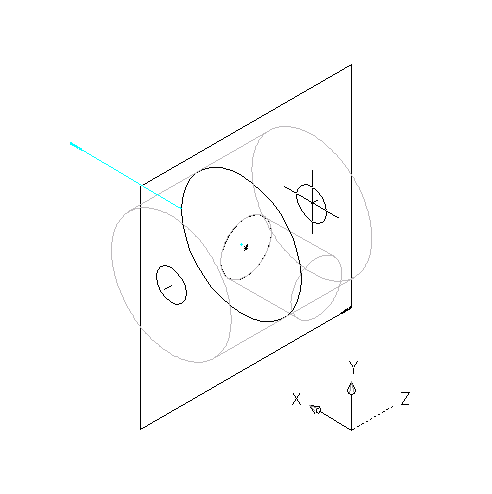
- To specify the third connection point, right-click Connections in the part browser, click Add Connection, and select the connector location on the end of the branch.
- Press Enter to accept the default value for the third connector number.
- Pick a location to the left of the model to place the dimension of the circular profile of the branch in the model. Tip: Turn off object snaps if you are having problems selecting a position off the model.
A diameter dimension (D3) is added to the model and to Size Parameters in the part browser, and a third connector is added to Connections.

- To define the connection type for each connector, in the part browser, right-click a connector in Connections and click Edit.
The Connector Properties dialog box displays connector details and values, including domain, type, and shape.
Note: Domain and shape are view-only parameters. - For Type, click the type specified for each connector and then click
 .
. - In the Connection Types Selection dialog box, select the appropriate connection types.
Connector types are dependent on the related parametric fitting domain. For example, the Piping domain includes a connection type called “Same Connection”. When “Same Connection” is configured for a pipe object that is attached to a Hub, the pipe connection type will not inherit the connection type on connector 1 of the Hub, as happens with other connection types. Rather, it will inherit the connection type on connector 2 of the attached Hub.
Tip: You can select connection types regardless of gender (male or female). Pipe connectors are assigned as undefined type by default. An undefined connection type creates a valid connection between all types of connectors when inserted in a drawing.