All AutoCAD MEP 2022 toolset objects have one or more smart connectors (connection points) that enable them to connect intelligently to appropriate objects and to transfer information such as shape, size, and system. Some objects, such as receptacles, require a single connector. Other objects, such as plumbing elbow fittings, require multiple connectors. You add connectors to style-based objects by adding connectors to the styles that define the objects. You can also remove connectors from styles, or change their type and location.
Note: For detailed information on configuring connectors for device styles and for plumbing fitting styles, both of which have unique considerations, see Configuring Connectors for Device Styles and Configuring Connectors for a Plumbing Fitting Style. For information on configuring the connectors of catalog-based content, such as MvParts and fittings for ducts, pipes, cable trays, and conduits, see Customizing Catalog-Based Content.
To configure the connectors of a style
- Open the drawing that contains the style.
- Open the style by doing one of the following:
- Click

 .
. In the left pane, navigate to the style, and select it.
- In the drawing, select an object that uses the style, then click the object’s contextual ribbon


 .
.
- Click
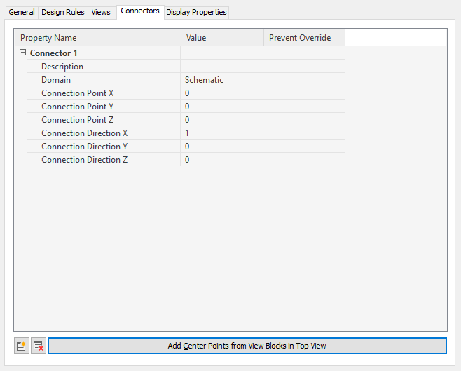
- Click the Connectors tab.

- For Description, enter a descriptive name, such as Air_Supply.
- For Domain, select a domain. For some types of styles, only a single domain is available.
- Specify values for connection points X, Y, and Z, or click Add Center Points from View Blocks in Top View to create a centered connector.
Danger: Use caution when modifying the connection points on connectors or removing connectors. Either can break the connectivity between objects because the connector is modified in or removed from all instances of the style in the drawing.
- If you want to add a connector, click
 , and configure the connector properties.
- If you want to remove a connector, select the connector, and click
 .
.
- Click OK.