After you finalize the model of your part, you need to define insertion behavior to ensure that your part can be placed correctly in a drawing. Insertion behavior includes specifying the placement point, or insertion point, that is used when placing the part in a drawing, and specifying the trim lengths for parts, such as fittings, that require other components to be trimmed when placing the part in a run.
The Auto Layout option in the Content Builder Options dialog box controls whether trim lengths and placement points can be defined for a part. When you enable this option, an Autolayout Data folder is available in the part browser that includes commands for adding trim lengths and placement points.
Trim Lengths
Trim lengths are available only when creating a parametric fitting. Configured to work with the Auto Layout option enabled, trim lengths define the length dimensions used to trim other components to make room for a new fitting. For example, when you add a tee to an existing run in your drawing, the segment is trimmed to the length of the trunk, creating 2 individual segments, 1 on either side of the fitting.
Each trim length is defined from the center, or intersection point, of the fitting to an end, or connection point, of the fitting. To ensure components are trimmed correctly when placing a parametric part into a drawing, you must define trim lengths for the part in a specific order—left to right, then bottom to top. The number of trim lengths required for a part depends on the type of fitting and the number of connection points, as shown next:
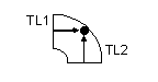
Elbows require 2 trim lengths
Reducers require 2 trim lengths

Tees require 3 trim lengths
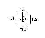
Crosses require 4 trim lengths
To add a trim length, you select valid node points that are displayed in the model and define a distance for the length. The following illustration shows how trim lengths for a tee fitting would be defined:
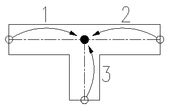
A tee has 3 trim lengths: 2 are defined from the center point of the trunk to each end of the trunk legs (1 & 2), and the third is defined from the center of the trunk to the end of the branch leg (3).
Placement Points
For parametric MvParts, the placement point is the insertion point used to place the part in a drawing. You simply specify a point in your model for the placement point. For parametric fittings, the Auto Layout advanced option in the Content Builder Options dialog box enables automatic part insertion during layout. The connection 1 position is the insertion position, which can be toggled through.