The AutoCAD MEP 2022 toolset display system controls how objects appear in a viewport. By specifying the objects for display and the direction from which to view them, you can produce different displays, such as plan layouts, 3D models, isometric riser diagrams, and schematic diagrams. Establishing standard displays helps maintain consistency across multiple drawings.
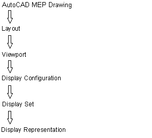
Three main components comprise the AutoCAD MEP 2022 toolset display system:
- Display representations for controlling how individual objects are displayed
- Display sets for grouping display representations of objects
- Display configurations for assigning display sets to view directions
These components are hierarchical in nature. Each display configuration contains some display sets, and each display set contains some display representations. The components work together to create the display system as follows:
Most AutoCAD MEP 2022 toolset objects have 1 Line, 2 Line, Model, and Plan display representations. This is because these are the most common design scenarios that require different views of a building system.
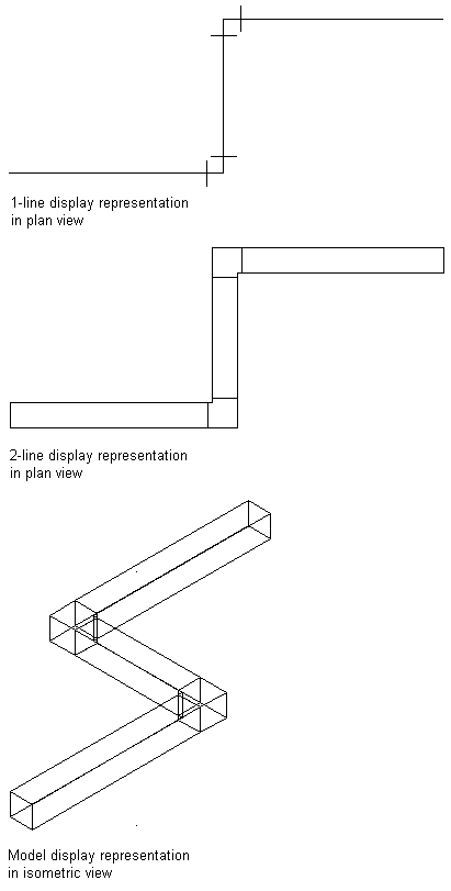
Some building systems objects, such as label curve objects and schematic objects, have only a general display representation because the display of these objects does not change in different views.
The sample templates have default display settings for new and tiled viewports. Default drawing settings guide new users. They also help more experienced CAD managers maintain consistency across project drawings by customizing the sample templates or creating new templates with different display settings.
- To specify the default display settings for an individual drawing, click

 Utilities Drawing Setup.
 - Click the Display tab on the Drawing Setup dialog box.
Display Manager
The Display Manager is the central location for the display system components in your AutoCAD MEP 2022 toolset drawings. You set up display configurations, display sets, and display representations in the left pane of the Display Manager. The right pane details information about a selected display system component.