You can convert a set of schematic symbol styles to their individual components: the style settings and the AutoCAD® blocks used by the style views. The output of the conversion process includes:
- a set of drawings that contain the AutoCAD blocks. The process creates one drawing per view block per style, so each drawing contains a single block definition.
- a symbol conversion script (Custom Content File or CCF file) that contains the style settings. The script contains not only the values for the style settings, but also the file path locations of the output drawings that contain the AutoCAD blocks.
Typically, you use this process when you have a set of existing schematic symbol styles that you want to customize. You convert the styles to their individual components, customize the components (the blocks and the style settings in the script), and then use the modified script to convert the modified blocks to new styles.
To convert a set of schematic symbol styles to their individual blocks
- Click

 .
.
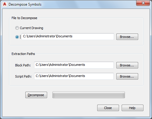
- In the Decompose Symbols dialog box, for File to Decompose, select the drawing (DWG file) that contains the schematic symbol styles to convert:
If you want to… then… convert the schematic symbol styles in the current drawing open in AutoCAD MEP 2022 toolset click Current Drawing. convert the schematic symbol styles in a drawing stored locally on your computer click the radio button beside the file path, click Browse, select the drawing file, and click Open. - For Block Path, click Browse, and select the folder in which to place the drawings that contain the AutoCAD blocks used by the views in the schematic symbol styles. Click OK.
If the selected folder already contains drawings, then during the conversion process, you will be prompted about overwriting drawings with the same name.
Note: Like all AutoCAD® blocks, the blocks in the output drawings are stored in an invisible data area called the block definition table. For more information, see . - For Script Path, click Browse, and select the file name of the symbol conversion script to create:
If you want to… then… create a new script in the Select File dialog box, specify the location for the new script, enter a name, and click Save. overwrite the contents of an existing script in the Select File dialog box, select the drawing, click Save, and then click Yes to confirm that the contents of the drawing can be overwritten. - Click Decompose.
The software converts the schematic symbol styles into the blocks used by the style views and generates an associated script based on the style definitions.
Note: Because a schematic symbol style specifies only the positions of the connectors and not the method in which they were initially specified, the script sets the default value of the Connector Placement property of all connectors to Specify. As a result, before you reuse the conversion script to create new schematic symbol styles, you might need to modify these values.
You can now modify the blocks and the script, and then use them to create new schematic symbol styles based on your modifications. For more information, see Converting Blocks to Schematic Symbol Styles.