You can create a custom duct fitting when the required fitting is not available from the part catalog or you have a unique design. You create custom fittings by converting AutoCAD lines, arcs, and polylines into AutoCAD MEP 2022 toolset objects with connectors. Part properties, such as size, shape, and system definition are inherited from the connecting parts to maintain system integrity. Custom fittings are style-based objects accessible through the . Each custom fitting you create represents a single style.
To create a custom duct fitting
- Draw the centerlines with lines, polylines, or arcs.
Typically, the centerline is drawn connecting ductwork and can be any combination of AutoCAD lines, arcs, or polylines. See the next illustration.
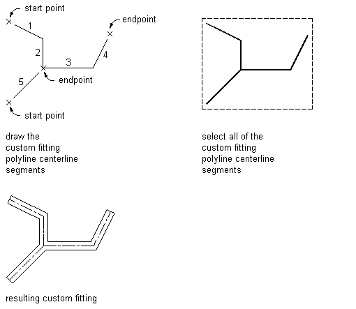
Defining a custom fitting polyline centerline
Note: If you draw linework from endpoints of an existing duct, the shape and size of the duct is inherited by the end segment of the fitting that you create. - Click
 .
.
- Select the polylines, lines, or arcs that represent the centerline of the custom fitting, and press Enter.
- In the Create Custom Fitting dialog box, enter a name, and select a system.
- Specify the shape and size for the start and end of each segment, and then select Mitered End if an end is mitered.
Use the to view the segment you are specifying properties for. As you step through the Create Custom Fitting dialog box, the Object Viewer highlights the current segment.
- If the properties assigned to the current segment are the same for all segments, select Apply to All Segments.
- If the properties of the next segment are different from those of the current segment, click Next.
The Next button is not available if you select Apply to All Segments.
- Click Finish, and enter y (yes) to erase the original centerline geometry or n (no) to keep the original geometry in the drawing.
- Press Enter. Note: If any size or shape properties of the segments are incomplete, the custom fitting cannot be created and the Missing Size or Shape Information error message is displayed.