Use this procedure to convert AutoCAD® solids, mass elements, blocks, or multi-view blocks (MvBlocks) into multi-view parts (MvParts). MvBlocks, like MvParts, can be viewed from different directions, but MvBlocks cannot connect intelligently with systems.
Architectural drawings referenced in an AutoCAD MEP 2022 toolset drawing can contain solids, mass elements, and MvBlock parts that may be useful as MvParts. You can convert MvBlocks to MvParts even if the MvBlock exists in a reference drawing.
This procedure is the same for mechanical, piping, electrical, and plumbing parts.
- Select the element or block to convert, right-click, and select Convert to
 Multi-view Part.
 - In the Multi-view Part Convert - Behavior dialog box, specify a name for the new part.
- Specify a part type for Type.
- Specify a category for Subtype.
- Specify a layer key for the new part.
- Click Next.
- In the Multi-view Part Convert - Connectors view, right-click the MvPart name and select a connector type.
- In the Part Family Connector Properties dialog box, specify the properties for the connector.
- Click OK.
- Continue adding connections for the part.
- To specify the location of a connection, select a connection, right-click, and select Edit Placement. Note that the MvPartBuilder - Connector Editor is displayed in your workspace.
- Select Position for Connector.
- Specify the placement for the connector on the MvPart. Note: Use object snaps to snap the connector placement to linework in the block drawing. When you are editing connector placement, you can make it easier to select geometry by using tools such as 3D Orbit and Pan to change the part view.
- If the connector has a flow direction, you can specify a vector to indicate the direction, or you can specify the coordinates in the Normal field under Connector Geometry. For example, a pipe connector with an outflow in the downward direction has the normal coordinates of 0,0,-1.
- To specify the placement of other connectors, select a connector at the top of the Connector Editor and specify the location on the MvPart.
- When you have finished, click OK to close the Connector Editor.
- If you want to change connector properties, select a connector in the Multi-view Part Convert - Connector dialog box, right-click, and select Modify.
If you want to change connector placement, direction, or size, right-click a connector and select Edit Placement. Use the Connector Editor to make changes.
- Click Finish.
The resulting MvPart can now be connected to specific building systems. Note that the original block still exists; the MvPart is created as a separate entity and placed in the same location.
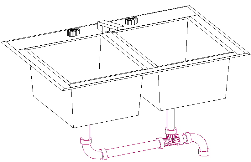
An example of a MvBlock sink that was converted to an MvPart. The sink can now connect to piping for the waste system.
The MvPart exists in the drawing but is not added to a part catalog. You can add multiple instances of a converted MvPart by copying and pasting it in a drawing. You can modify a converted MvPart by selecting it, right-clicking, and selecting Edit MvPart Style. If you want to create an MvPart from a block, and include it in a part catalog, use the Content Builder.