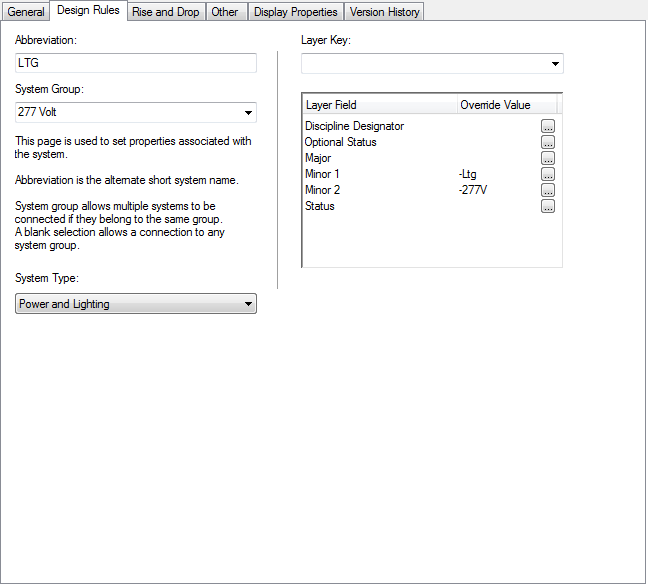
The design rules of a system definition are properties that determine the behavior and display of the system.
| Property | Description |
|---|---|
| Abbreviation | Identifies the system to which the parts are assigned. This is a short system name, typically two or three characters in length. The abbreviation can be used when labeling objects and creating schedules. |
| System Group | Identifies the group of related systems with which the system is associated. System groups allow you to connect different systems while maintaining their individual system properties. For more information, see About System Groups. |
| System Type | Identifies the type of system. Available in electrical and plumbing systems only. Power & Lighting and Cable Tray are 2 examples of system types in electrical systems. Every electrical system must have a specified system type. Hot Water and Waste are 2 examples of system types in plumbing systems. A plumbing system does not require a system type. However, sanitary pipe systems that use gray water or black water must specify the System Type as Waste. Otherwise, the Size Sanitary Pipe command does not recognize the system as a sanitary pipe system, and you are not be able to size the pipe run. |
| Layer Key | Identifies the layer to which objects in the system are added. |
To specify the design rules of a system
- Within the domain-specific workspace, click

 , and click one of the following:
 -

-

- .

- .

- .

-
- In the left pane, select the system, and, in the right pane, click the Design Rules tab.

Design Rules tab for an electrical system definition
- Configure the design rules:
If you want to specify… then… system abbreviation for Abbreviation, enter an abbreviation. system group for System Group, select or enter a group name. New names are added to the list of existing names. Note:A blank selection allows a connection to any system group.

system type for System Type, select the applicable component to connect to the system. The list is not customizable.
Note: For Electrical or Plumbing system definitions onlylayer key for Layer Key, select a layer key. The list of available layer keys depends on the layer key style specified for the drawing. To create a layer key override, click [...] beside the appropriate Layer Field, select an override value in the dialog box, and click OK.