Each part size represents a real-world building systems part, such as a piece of equipment, that has different representations in different views. In the block-based building environment, 2-dimensional (2D) orthographic view blocks can be generated from the 3D model of the part size. Standard AutoCAD® blocks representing the plan, elevation, and model views of a part are grouped together to create an individual part size. Typically, each part size has 6 orthographic view blocks: 1 for each view direction (top, bottom, front, back, left, right). The following illustrations represent the 6 orthographic view blocks for an air handling unit.

Top and bottom orthographic view blocks
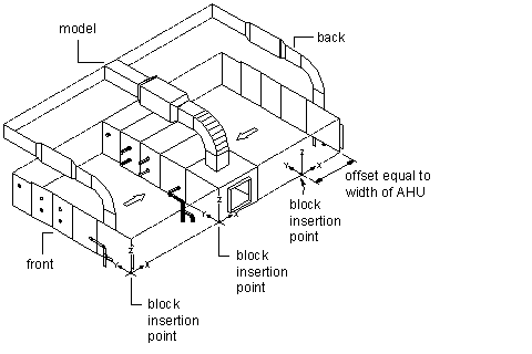
Front and back orthographic view blocks
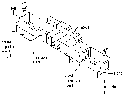
Left and right orthographic view blocks
The insertion point, or base point, is used as a reference for positioning the block upon insertion. All view blocks share a common insertion point of 0,0,0 in the world coordinate system (WCS) that reflects the same point on the model block. The location of the insertion point directly affects the placement of the part size when you add it to your drawing.
The previous illustrations show the insertion point of the model view as the right corner of the bottom edge of the front side. The top and bottom views have an insertion point at the right corner of the front edge, with the top-view insertion point offset by the height of the air handling unit. The front and back views have an insertion point at the right corner of the bottom edge, with the back-view insertion point offset by the width of the air handling unit. The left and right views have an insertion point at the bottom-front corner, with the left-view insertion point offset by the length of the air handling unit.
Once view blocks are generated, they are assigned to the appropriate display representation based on view direction, name, and view block. You can change the default assignments as needed. It is possible to assign the same view block to multiple view directions, such as front and back, depending on the part symmetry. The view block assignments are as follows:
| View Block | Display Representation | View Direction |
|---|---|---|
| Top | 1 Line | Top |
| 2 Line | Top | |
| Bottom | 1 Line | Bottom |
| 2 Line | Bottom | |
| Front | 1 Line | Front |
| 2 Line | Front | |
| Back | 1 Line | Back |
| 2 Line | Back | |
| Left | 1 Line | Left |
| 2 Line | Left | |
| Right | 1 Line | Right |
| 2 Line | Right | |
| Model | 1 Line | 3D |
| 2 Line | 3D | |
| Model | All directions | |
| Symbol | Schematic | All directions |