Use this procedure to add work planes on which to create the geometry of the model. To avoid confusion, work with only one work plane visible, unless you are using offset or reference work planes. You can create additional work planes as you need them to build the model. It is helpful to use offset work planes to locate multiple sides of a part, such as both faces of an air terminal. It is helpful to use reference work planes to locate geometry on your parts, such as knockouts for a junction box or taps on a tank.
- In the part browser, expand Modeling.
- Right-click Work Planes and click Add Work Plane.
The Create Work Plane dialog box is displayed.
- Click Default and then click OK.
The ZX plane, YZ plane, and XY plane work planes are created.
- To view the work planes in the modeling area, on the floating View panel, click
View drop-down
 .
.
- In the part browser, expand Work Planes.
When you select a work plane in the part browser, the work plane is highlighted in the modeling area.

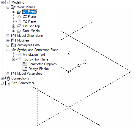
Selecting the ZX plane
- To avoid confusion, work with only one work plane visible at a time. In the part browser, right-click ZX Plane and click Visible. Do the same for YZ Plane.
The ZX Plane and YZ Plane icons are unavailable (shaded) and the XY plane is the only visible work plane in the modeling area.