In display configurations that use 2-line display representations for ducts and fittings, you display center lines on the ducts and fittings by turning on the visibility of the Center Line display components (in the display representations).
However, in display configurations that use Plan display representations, you have more flexibility. You can:
- Display or hide the center lines on all ducts and fittings
- Display or hide the center lines on ducts and fittings of specific shapes
- Display or hide the center lines on flexible ducts
- Extend the center lines of round takeoffs and oval takeoffs to the center lines of mains
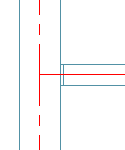
In the following image, center lines are displayed on the round ducts and fittings to the left of the multi-shape transition fitting, but they are not displayed on the transition fitting or the rectangular duct on the right.

If you create a 2D section or 2D elevation using a display set that uses the Plan display representations, the section or elevation also shows the center lines as specified.
To display center lines on ducts and fittings in Plan display representations
- Click

 Options.
 - Click the MEP Display Control tab.
- Under Center Line Display, specify the ducts and fittings on which you want to display center lines. Note: The Display on Multi-shape Fittings setting works in conjunction with the shape-dependent settings. The center line on the fitting is displayed if center lines are enabled for the shape corresponding to at least one of its connectors.Attention: To display center lines on all ducts and fittings regardless of shape, select all of the options. For center lines to be visible in display configurations using Plan display representations, these settings must be configured as required, and the Center Line display components must be set to Visible (which you do later in this procedure). You cannot complete the latter task alone.
- If you want to display center lines on flexible ducts, select Display Center Line on Flex Ducts. Note: If you are using duct system definition overrides, and you do not want to display center lines on the flexible ducts assigned to those systems, deselect this option. A system definition override that turns on the Center Line display component does so for all duct objects, including flexible ducts. However, center lines are not displayed on any flexible ducts unless this option is selected.
- If you want to extend the center lines on takeoffs to the center lines of the mains, select Extend Center Line for Takeoffs.
 Note: The center line on a takeoff is displayed if center lines are enabled for the shape corresponding to the branch connector. It is extended to the main if you select Extend Center Line for Takeoffs, and the takeoff is round or oval (not rectangular or multi-shape).
 - Click

 .
. 
- In the left pane of Style Manager, select any system definition, and in the right pane, click the Display Properties tab.
- Select the Plan display representation, and click
 . Note: Accessing and configuring a display representation in this way automatically applies the changes to the same display representation for all duct objects (ducts, duct fittings, custom duct fittings, and flexible ducts). You can achieve the same results by configuring the display representations using Display Manager, but this requires you to configure the display representation for ducts, repeat the changes in the same display representation for duct fittings, repeat them again for custom duct fittings, and so on.
 - In the Display Properties dialog box, click the Layer/Color/Linetype tab.
- Click the icons under Visible to turn on the Center Line display components.
- Configure the remaining display properties of the Center Line display components as required.
In the following steps, you turn on the visibility of the Center Line display components in the Plan display representations for all duct objects.
If needed, you can also apply system-level overrides or style-level overrides.