You can create 2 types of content using Content Builder: parametric parts and block-based parts. To determine what type of part to create, it is important to understand how each type is defined, how the parts are used in AutoCAD MEP 2022 toolset, and what type is best for certain parts.
Parametric Parts
Parametric parts give you the flexibility to create parts that are dynamically sized according to size parameters. You define a parametric part by creating a 3D model of the part and assigning variables, or parameters, to control its shape and size. Parameters are defined by individual values, lists of values, or calculated values based on equations. When the part is placed in your drawing, you specify values for the parameters and the part is dynamically built to reflect the specified shape and size. Parametric parts enable you to create a single 3D model for a part family that can be updated to represent multiple part sizes. Parametric parts enable you to define millions of parts through a single model, depending on the number and type of parameters defined.
It is beneficial to create parts like equipment and fittings as parametric parts. Equipment, such as an air terminal, a junction box, or a tank, share the same geometric features; however, the features change in size according to the design. Following are examples of custom parametric parts for each module.
- Mechanical: A 4 x 4-inch rectangular floor register looks the same as a 6 x 6-inch rectangular floor register, except for the longer length and width. By creating a parametric part, you can create a 3D model of a rectangular floor resister and assign parameters for the length and width that can change in size. When the register is placed in your drawing, you can specify the length and width, and the register is dynamically built to match.

Viewing different-sized air terminals
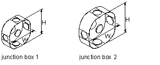
- Electrical: A 13-hole junction box for 1-inch conduit looks the same as a 13-hole junction box for 3-inch conduit, except for the size of the inlet for the conduit connection. By creating a parametric part, you can create a 3D model of a 13-hole junction box and assign a parameter for the conduit connection that can change in size. When the junction box is placed in your drawing, you specify the size of the conduit and the junction box is dynamically built to match.

Viewing different-sized junction boxes
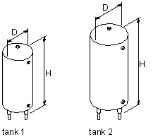
- Plumbing: A 120-gallon storage tank looks the same as a 350-gallon storage tank, except for the height and diameter. By creating a parametric part, you can create a 3D model of a storage tank and assign parameters for the height and diameter that can change in size. When the storage tank is placed in your drawing, you can specify the height and diameter, and the tank is dynamically built to match.

Viewing different-sized tanks
Fittings such as elbows, tees, and crosses also share geometric features that change in size according to the design. For example, a round 2-inch elbow looks the same as a round 6-inch elbow, except for the diameter and elbow radius. By creating a parametric part, you can create a single 3D model of a round elbow and assign parameters for the diameter and elbow radius that can change in size as needed. When the elbow is placed in your drawing, you can specify the diameter and radius and the elbow is dynamically built to match.

Viewing different-sized elbows
Block-Based Parts
A block-based part is a multi-view part (MvPart) whose geometry is based on individual AutoCAD® blocks. Each part size is associated with a unique 3D model block, to which you specify basic information such as view representations and connector placement. 2-dimensional (2D) block representations are generated for each part size. When the part is placed in your drawing, you select a specific part size, and the unique representation of the part is added to your drawing.
You create equipment, referred to as MvParts, as block-based parts. MvParts, such as air handling units, motor control centers, or pumps, typically consist of a group of unique parts with their own geometric features. Shape, size, connection points, and properties such as manufacturer or material may differ.
For example, a gas air handling unit and an electric air handling unit are not only different in shape and size but also in placement of connection points and types of connectors.

Viewing different air handling units