During the process of converting blocks to device styles, you might need to modify the device conversion script that you are using.
If the conversion script was initially generated by the software as a result of converting existing device styles to blocks, you need to modify the script to reflect the customizations that you want before you use the same script to convert the blocks to new device styles.
If you created the conversion script, you might want to modify the script to change one or more settings before repeating the conversion process. Although you can also change the settings using the Style Manager, the changes are overwritten if you subsequently repeat the conversion process.
You modify a device conversion script using the Edit Device Script dialog box.
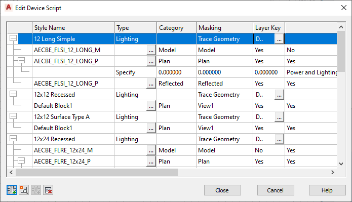
In the dialog box, the displayed settings change depending on whether you select a device style, a device view, or a connector in the table. For example, in the following images, notice how the heading names differ depending on the selected object.

Selected style

Selected view

Selected connector
To modify a device conversion script
- Click


 .
.
- In the Batch Convert Devices dialog box, under Conversion Script File, for Path specify the device conversion script (CCF file) to use to convert the blocks to device styles. Then, click Edit.
- In the Edit Device Script dialog box, modify the script:
If you want to… then… modify a device style select the style, and modify its properties using the available options. add a device style click  , select the new style, and modify its properties.
 modify a view for a device style select the view, and modify its properties using the available options. For example, you might want to specify a different source AutoCAD® block for the view. To do so, you can modify the block definition in the drawing specified in the Source Block property, or you can specify the file path of a different drawing.
add a view to a device style select the style to which to add the view, and click  . Select the view, and modify its properties.
 modify a connector for a device style select the connector, and modify its properties using the available options. Note: If you are using a script generated using the Decompose Devices command, you might need to specify a value for the Connector Placement property for some connectors. The script sets this property to Specify by default. You can select- Specify, and then enter the X, Y, and Z coordinates
- Center to place the connector at the center of the view block
- Insert to place the connector at the insertion point of the view block
- Node to place a connector at each AutoCAD point object in the view block
add a connector to a device style select the view to which to add the connector, and click  . Select the connector, and modify its properties.
 delete a device style, a view, or a connector select the style, the view, or the connector, and click  .
. To assist you in modifying the script, the sections that follow identify where you configure the same device style properties in the user interface. For more information on device style settings, see Configuring Styles for Devices and Panels and Working with Styles.
- Click Close to save your changes and return to the Batch Convert Devices dialog box to create the device styles.
For more information, see Converting Blocks to Device Styles.
Style Properties
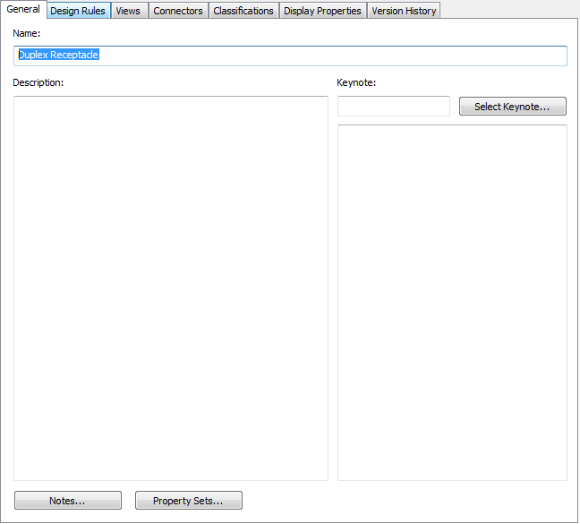
The Style Name property in the device conversion script displays on the General tab of the Style Manager. On the tab, the property is called Name.
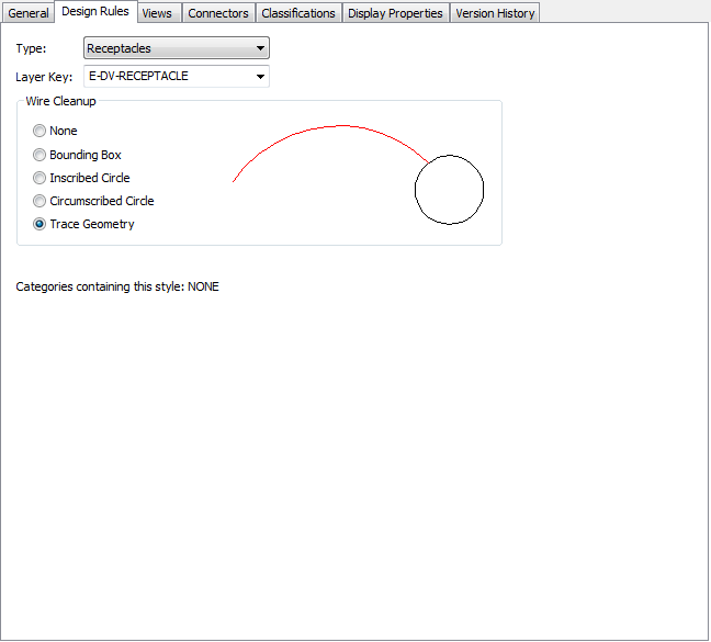
The Type, Layer Key, and Masking properties in the script display on the Design Rules tab of the Style Manager. On the tab, the Masking property is called Wire Cleanup.
The Category property in the script does not display in the Style Manager. Device categories are the mechanism by which you group the devices (device styles) in the Select Device worksheet, making it easier to browse the available devices. You create and manage device categories directly in the worksheet; for more information, see Creating Categories in AutoCAD MEP 2022 toolset.
If you enter a name in the Category property of the device conversion script, the software adds the device (device style) to the category. If the category does not exist, it is created in the style drawing.
View Properties
The view properties in the device conversion script display on the Views tab of the Style Manager. On the tab, the Annotation View property is called Annotation Block.
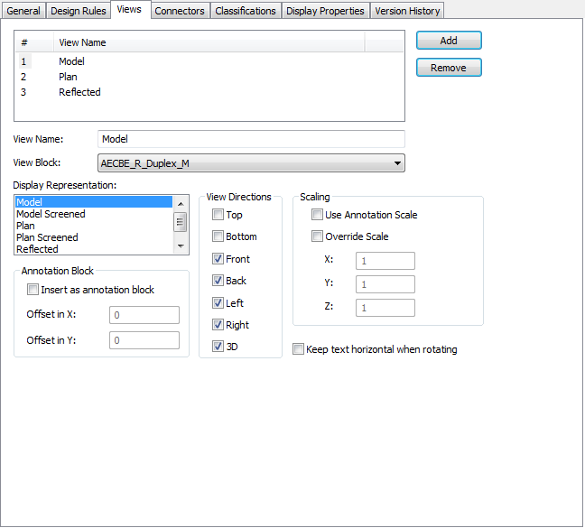
The Source Block property in the script does not display on the tab. When you create a style view using the Style Manager, you do not specify the file path of the drawing containing the source AutoCAD block, because you are limited to selecting a block in the current drawing.
Connector Properties
The connector properties in the device conversion script display on the Connectors tab of the Style Manager. On the tab, the Connector Type property is called System Type.
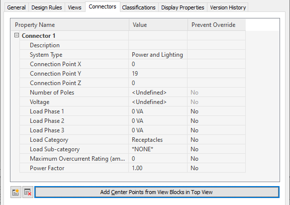
The Connector Placement property in the script does not display on the tab. In the Style Manager, you can only specify a connector position by entering the X, Y, and Z coordinates, or by placing the connector at the center of the block, using the options shown in the image.