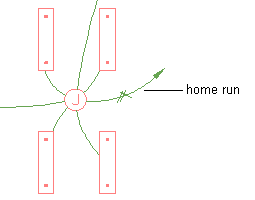
A home run is a wire that graphically represents the wiring of a circuit to a central location that acts as the distribution point for the power, typically, a panel. You do not need to connect the home run to the panel. You can draw the home run in the direction of the panel, as is common practice.
The appearance of the home run is determined by the annotation properties of the wire style.
While you can use a single home run to represent the connection of one or more circuits to a single panel, sometimes devices are assigned to multiple circuits on different panels. For example, you might have a lighting fixture with 2 electrical connectors, where the first connector is assigned to a circuit on a panel for normal lighting, and the second connector is assigned to a circuit on a panel for emergency lighting. When a device is assigned to multiple circuits on multiple panels, you must add a home run to each panel. This allows you to subsequently tag each home run with the correct panel information. Make sure the locations of the electrical connectors in the device style are not the same, so you are able to draw a home run from each connector.
To draw a home run
- Select an existing wire on the circuit, and click


- Using electrical snaps, select a device in the circuit.
- Press Enter, and specify a point in the direction of the circuit’s panel.