You can draw ductwork in various sizes and shapes. You can automatically place fittings, such as elbows and tees, as you draft. You can also manually add fittings to your runs, which is beneficial when using fittings not specified in the duct layout preferences.
After you initially lay out your mechanical equipment, you can draw ductwork to connect equipment and create networks. AutoCAD MEP 2022 toolset includes many features that streamline the design and drawing of duct runs.
The process for adding duct runs is the same. You can add duct as 1-line objects as you design preliminary routes, and then modify them to 2-line objects as you specify properties, such as size and connection type. 1-line duct runs appear as single-line representations while 2-line runs display the actual geometry of the duct, even in isometric views. You do not necessarily need to draw runs as 1-line elements at first. You can draw defined 2-line duct any time.
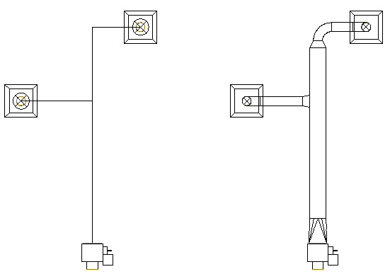
On the left, a top view of a 1-line duct run and on the right, a defined 2-line duct run.
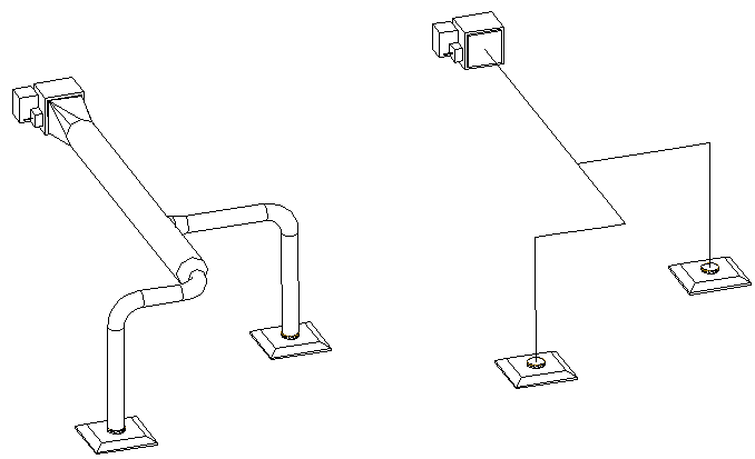
1-line and 2-line duct runs can be routed 3 dimensions.
You can size duct systems using AutoCAD MEP 2022 toolset engineering analysis tools. You can use a duct system size calculator to size duct systems, and you can use instant duct size calculators in the Add dialog box and Modify dialog box to size individual segments.