Creates multiple types of dimensions within a single command session and provides the ability to specify tolerances or fits as appropriate.
Summary
The supported dimension types range from vertical, horizontal, aligned, and rotated linear dimensions, to angular dimensions, to radius, diameter, jogged radius, and arc length dimensions, to baseline and chain dimensions. If required, you can change the dimension type using command line options.
List of Prompts
The following prompts are displayed.
Select object
Automatically selects an applicable dimension type for the objects you select and displays the prompts corresponding to that dimension type.
| Selected object type | Action |
|---|---|
| Arc | Defaults the dimension type to radius dimensions. |
| Circle | Defaults the dimension type to diameter dimensions. |
| Line | Defaults the dimension type to linear dimensions. |
| Dimension | Displays the Power Dimensioning dialog box enabling you to modify the dimension options. |
| Ellipse | Defaults to options set for selecting a line. |
First extension line
Creates a linear dimension when you select two points.
- Second extension line origin
- Specifies the second point that defines the linear dimension.
- Dimension line location
- Specifies where to place the dimension line. Depending on the direction you move the dimension, the dimension changes to a horizontal, vertical or aligned dimension.
Linear
Creates a linear dimension with a horizontal, vertical, or rotated dimension line.
- Horizontal
- Sets the dimension type to horizontal linear dimensions.

- First extension line origin - Specifies the first point that defines the horizontal linear dimension (1 in the illustration).
- Second extension line origin - Specifies the second point that defines the horizontal linear dimension (2 in the illustration).
- Dimension line location - Specifies where to place the dimension line. The dimension line moves only in the vertical direction (3 in the illustration).
- Vertical
- Sets the dimension type to vertical linear dimensions.

- First extension line origin - Specifies the first point that defines the vertical linear dimension (1 in the illustration).
- Second extension line origin - Specifies the second point that defines the vertical linear dimension (2 in the illustration).
- Dimension line location - Specifies where to place the dimension line. The dimension line moves only in the horizontal direction (3 in the illustration).
- Aligned
- Sets the dimension type to aligned linear dimensions.

- First extension line origin - Specifies the first point that defines the aligned linear dimension (1 in the illustration).
- Second extension line origin - Specifies the second point that the aligned linear dimension (2 in the illustration).
- Dimension line location - Specifies where to place the dimension line. The dimension line moves only in the direction perpendicular to the two points (3 in the illustration).
- Rotated
- Sets the dimension type to rotated linear dimensions.

- Angle of dimension line - Specifies how far to rotate the dimension line.
- First extension line origin - Specifies the first point that defines the rotated linear dimension (1 in the illustration).
- Second extension line origin - Specifies the second point that the rotated linear dimension (2 in the illustration).
- Dimension line location - Specifies where to place the dimension line. The dimension line moves only in the direction perpendicular to the specified angle (3 in the illustration).
- Placement options
- Provides options to override the default distance snap settings.
- Select object - Specifies an object to use as the base for the distance snap calculation.
- Options - Displays a dialog box, which enables you to override the snap distance or turns distance snap on or off, temporarily.
Angular
Creates an angular dimension showing the angle between three points by or the angle between two lines.
- Vertex
- Creates a dimension based on three points you specify.

- Vertex - Specifies the point to use as the vertex of the angle (1 in the illustration).
- First angle endpoint - Specifies one of the lines that form the angle (2 in the illustration).
- Second angle endpoint - Specifies the other line that forms the angle (3 in the illustration).
- Dimension arc line location - Specifies where to place the dimension arc line (4 in the illustration). Depending on the position of the dimension, the quadrant for the dimension changes.
- Quadrant - Specifies the quadrant to which the dimension is locked. When quadrant behavior is on, the dimension line extends past the extension line when the dimension text is outside of the angular dimension.
- Arc
- Uses the endpoints of the selected arc and its center as the defining points for a three-point angular dimension. The center of the arc is the vertex.
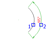
- Dimension arc line location - Specifies where to place the dimension arc line (2 in the illustration). Depending on the position of the dimension, the quadrant for the dimension changes.
- Quadrant - Specifies the quadrant to which the dimension is locked. When quadrant behavior is on, the dimension line extends past the extension line when the dimension text is outside of the angular dimension.
- Circle
- Uses two points on a circle and the center of the circle as the defining points for a three-point angular dimension. The center of the circle is the vertex and the first selection point (1 in the illustration) is the origin of the first extension line.

- Second angle endpoint - Specifies the origin of the second extension line (2 in the illustration).
- Dimension arc line location - Specifies where to place the dimension arc line (3 in the illustration). Depending on the position of the dimension, the quadrant for the dimension changes.
- Quadrant - Specifies the quadrant to which the dimension is locked. When quadrant behavior is on, the dimension line extends past the extension line when the dimension text is outside of the angular dimension.
- Line
- Creates a dimension for the angle between two lines. The line you selected (1 in the illustration) is the first line that defines the angle.

- Second line - Specifies the other line that forms the angle (2 in the illustration).
- Dimension arc line location - Specifies where to place the dimension arc line. Depending on the position of the dimension, the quadrant for the dimension changes. If the dimension line does not intersect the lines you are dimensioning, additional extension lines extend one or both lines. The dimension arc line is always less than 180 degrees.
- Quadrant - Specifies the quadrant to which the dimension is locked. When quadrant behavior is on, the dimension line extends past the extension line when the dimension text is outside of the angular dimension.
Radial
Sets the dimension type to radius dimensions.
- Radius
- Sets the dimension type to radius dimensions.
- Select arc or circle - Specifies the arc or circle to create dimensions for.
- Dimension line location - Specifies where to place the dimension line. If you place the dimension off of an arc resulting in the dimension pointing outside an arc, AutoCAD Mechanical toolset automatically draws an arc extension line.
- Linear - Forces the dimension type to linear dimensions.
- Options - Displays the Radius Dimension Options dialog box enabling you to configure the appearance of the dimension.
- Diameter
- Sets the dimension type to diameter dimensions.
- Select arc or circle - Specifies the arc or circle to create dimensions for.
- Dimension line location - Specifies where to place the dimension line. If you place the dimension off of an arc resulting in the dimension pointing outside an arc, AutoCAD Mechanical toolset automatically draws an arc extension line.
- Linear - Forces the dimension type to linear dimensions.
- Options - Displays the Diameter Dimension Options dialog box enabling you to configure the appearance of the dimension.
- Jogged radius
- Sets the dimension type to jogged radius dimensions.
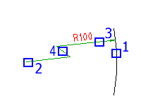
- Select arc or circle - Specifies the arc or circle to create dimensions for (1 in the illustration).
- Center location override - Specifies the point to use in place of the true center point of the arc or circle (2 in the illustration).
- Dimension line location - Indicates the angle of the dimension line (3 in the illustration). If you place the dimension such that the dimension points outside the arc, AutoCAD Mechanical toolset automatically draws an arc extension line.
- Jog location - Specifies where to place the jog (4 in the illustration).
- Arc length
- Sets the dimension type to arc length dimensions.
- Select arc or polyline arc segment - Specifies the arc or circle to create dimensions for.
- Dimension line location - Specifies where to place the dimension line. If you place the dimension off of an arc resulting in the dimension pointing outside an arc, AutoCAD Mechanical toolset automatically draws an arc extension line.
- Partial - Creates an arc length dimension for only a section of the arc.
Chamfer
Creates dimensions for a chamfer.
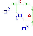
- Select chamfer line
- Specifies the chamfer to dimension (1 in the illustration). Press ENTER to exit the command.
- Select first object
- Selects the first of the two lines that form the chamfer (2 in the illustration).
- Select second object
- Selects the second of the two lines that form the chamfer (3 in the illustration).
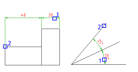
Baseline
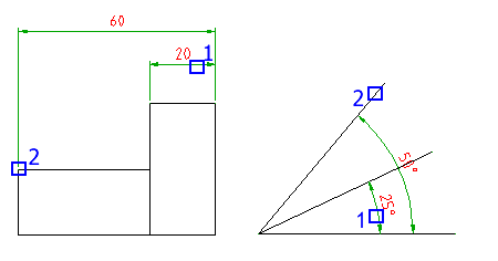
- Base dimension
- Specifies a linear or angular dimension to use as the base for the baseline dimension (1 in the illustration).
- Next extension line origin
- Specifies the next edge or angle to dimension (2 in the illustration).
- Select
- Respecifies the dimension to use as the base dimension.
Chain
- Base dimension
- Specifies a linear or angular dimension to use as the base for the chain dimension (1 in the illustration).
- Next extension line origin
- Specifies the next edge or angle to dimension (2 in the illustration).
- Select
- Respecifies the dimension to use as the base dimension.
Options
Displays the Power Dimension Options dialog box enabling you to pre-configure options for this command session.
Update
Updates fits and tolerances of dimensions that you select, to reflect the most current settings configured for text height and color in AMOPTIONS. It also updates the upper and lower deviating values of a fit, sometimes necessary when you stretch a dimension.