-
Click

 . Find
- On the Selection step of the wizard:
- From the View drop-down list, select Top or Bottom.
- Select all the parts required to define a complete screw connection.
- Verify that the check boxes adjacent to the parts that must be visible for the top/bottom view are selected and the others are cleared.
- Select the nominal diameter for the screw connection.
- Click Next. The wizard hides.
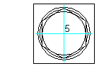
- Specify the insertion point (5). The Location step of the wizard displays.
- In the GL1 box, type the thickness of the first plate. Alternatively, you can click
 and measure the thickness of the plate.
 - If you selected two plates in the Selection step,
- In the GL2 box type the thickness of the second plate. Alternatively, you can click
 and measure the thickness of the plate.
 - If there is a gap between the two plates, in the Gap box type the thickness of the gap. Alternatively, you can click
 and measure the gap.
- In the GL2 box type the thickness of the second plate. Alternatively, you can click
- Click Finish. The screw connection is inserted.
Depending on the selected view, there are differences in the insertion process.