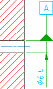
A datum identifier symbol identifies a datum feature for a feature control frame symbol.
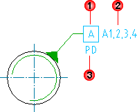
In addition to the datum identifier (1 in the illustration), AutoCAD Mechanical toolset supports datum notes (2 in the illustration) and thread notes (3 in the illustration) for standards that permit them. A datum note typically contains a series of datum targets, separated by commas (", "). Thread notes are typically placed on symbols attached to screw threads or gears. They specify which diameter to use as the datum. For example, in the above illustration, the thread note specifies that the pitch diameter is the datum.
Orthogonal Leaders
 |
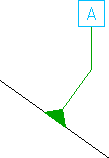 |
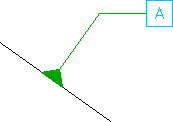
When you attach the symbol leader to an object, AutoCAD Mechanical toolset forces the first segment to be perpendicular to the attached object. The subsequent leader segment is forced to be horizontal or vertical.
Surface Extension Lines
If you move the start point of the leader beyond the end of a line or arc AutoCAD Mechanical toolset automatically draws extension lines. The default values for overshoot length and offset from end of leader is determined by the DIMEXE and DIMEXO system variables, respectively. AutoCAD Mechanical toolset does not create extension lines for splines.
Surface Indication Leaders
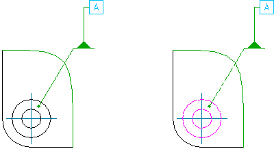
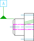
AutoCAD Mechanical toolset provides command line options to create surface indication leader. This enables symbol leaders to point to a surface rather than an edge. Using surface indication leaders you can indicate the datum using a top view rather than a side view. When the datum is on the far side of a component, you can specify options so that the surface indication linetype changes to a dashed style.
Attach to Annotations
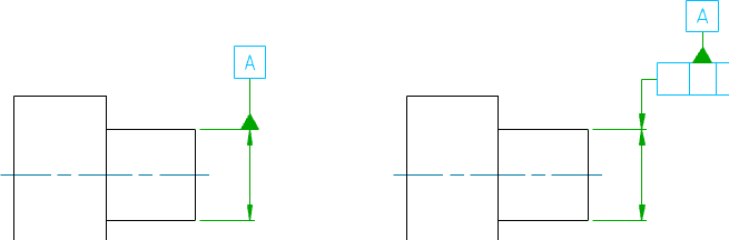
AutoCAD Mechanical toolset provides options to attach and align datum identifier symbols to annotations as shown in the above illustration.
Though not supported directly, you can attach a datum identifier symbol to a dimension as shown in the above image. When you place the start point of the symbol on the dimension, the arrows of the dimension and leader overlap. You achieve the appearance shown in the image by changing the arrowhead of the dimension to “none”.
Supported Drafting Standards
| Standard/Revision | Orthogonal Leaders | Surface Extension Lines | Surface Indication Lines | Datum Notes | Thread Notes |
|---|---|---|---|---|---|
| ANSI ASME Y14.5 M -1994 | Yes | Yes | |||
| ASME Y14.5M - 1982 | Yes | Yes | |||
| BSI EN ISO 1101:2013, BSI EN ISO 5459:2011 | Yes | Yes | |||
| BS 308 Part 3 -1990 | Yes | Yes | |||
| CSN EN ISO 1101:2013 | Yes | Yes | |||
| CSN 01 3138 -1994 | Yes | Yes | |||
| DIN ISO 1101:2008 DIN EN ISO 5459:2011 | Yes | Yes | Yes | Yes | Yes |
| DIN ISO 1101:2008 DIN EN ISO 5459:2008 | Yes | Yes | Yes | Yes | Yes |
| DIN ISO 1101:1983 DIN EN ISO 5459:1982 | Yes | Yes | |||
| GB/T 1182 -2008 | Yes | Yes | Yes | ||
| GB/T 1182 -1996 | Yes | Yes | Yes | Yes | |
| GOST 2.308-79 | Yes | Yes | |||
| ISO 1101:2012(E) ISO 5459:1981 | Yes | Yes | Yes | Yes | Yes |
| ISO 1101:2004 ISO 5459:1981 | Yes | Yes | Yes | Yes | Yes |
| ISO 1101:1983 ISO 5459:1981 | Yes | Yes | |||
| JIS B 0021 (1998) | Yes | Yes | Yes | ||
| JIS B 0021:1984 JIS B 0022:1984 | Yes | Yes | Yes |