When you create a parts list, its layout conforms to the settings saved with the current drafting standard.
Once a parts list is created, you can override most settings (See the Configuration and Setup Guide for information on how to change the defaults).
- Change the style of a parts list.
When you create a parts list, the style defaults to what is set in the drafting standard. Once the parts list is created, you can convert to any style. At any time you can convert a standard-based parts list to a custom parts list, or convert a custom parts list to a standard-based parts list.
- Add or remove columns.
Any component property that is visible in the BOM, but is not visible as parts list columns can be added after the parts list is created. Similarly, if you do not need any of the columns that are displayed by default, you can remove them.
- Move columns.
In the Parts List dialog box, columns can be moved by dragging them by their column headings.
- Resize columns.
In the drawing area, you can resize columns by dragging their grip points. Grip points are displayed when you select a parts list in the drawing area.
- Change the location of the header row.
You can specify where the insertion point for the parts lists is located. If the insertion point is at the upper left or upper right, the heading row is at the top of the parts list. If the insertion row is at the bottom left or bottom right, the heading row is at the bottom.
- Perform column splitting.
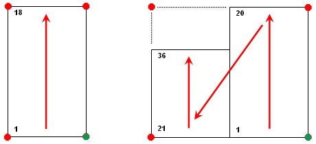
Column splitting refers to the ability for parts list columns to wrap, when the number of data rows exceed a threshold value you specify. The following image shows a parts list with 18 data rows and another with 36. Column splitting occurs when the number of rows exceeds 20. The insertion point is shown as a green dot.

Instead of specifying the threshold value, you can define the number of sections that the columns must split to. In this case the data rows are split evenly between the number of sections you define.