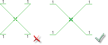
For the BOM Migration wizard to be able to extract information from non-AutoCAD Mechanical toolset drawings and populate data in BOM, the drawings in the project must meet these requirements.
Rules for Drawing Borders
- The drawing border must be a closed rectangle.
- The drawing border must not be rotated.
Rules for Title Blocks
- The title block must be a closed rectangle.
- One corner of the title block must coincide with the drawing border.
- The location of the title block (relative to the drawing border) must be the same across all drawings that match a given reference drawing.
- The locations of the cells within the title block must be the same across all drawings that match a given reference drawing.
Rules for Parts Lists
- The parts list must be located within the drawing border specified in the Select the drawing border step.
- The location of the parts list (relative to the drawing border), must be the same across all drawings that match a given reference drawing. Note:
This rule does not apply to drawings that use a Microsoft Excel spreadsheet for parts lists.
- The migration tools do not support floating parts lists. Hence, The parts list must be located in a corner of the drawing border.
- If the parts list is in the same corner of the title block, it must be directly above or below title block, forming a contiguous entity.
- The width of the parts list title row and the header row must be the same.
- If the parts list in the reference drawing does not contain a title row, none of the corresponding must contain a title row. However, if the reference drawing parts list has a title row, it is optional for the corresponding drawings.
- The data rows cannot contain split cells.
- The column headings within the spreadsheet must be identical to the column headings in the parts list in the corresponding reference drawing.
- If the spreadsheet has no header row, the order of columns in the spreadsheet must be identical to the parts list in the reference drawing.
- Extended parts list must be located side-by-side, or wrapped around the title block.
- The width of the extended parts list must be the same as the width of the main parts list.
Rules for Balloons
- The balloon type of a drawing must be the same as the reference drawing (and typical drawing) corresponding to it.
- Balloons must not overlap the parts list area or title block area.
- The leader length must be significantly larger than the balloon text height.
- There can be no more than 3 leader segments for a single balloon.
- A balloon must have a corresponding parts list entry or else that balloon is not migrated.
- The angle between the reference line and the leader must be from 90 through 180 degrees.

- The length of the leader must be significantly longer to that of the balloon size.
- All reference lines must be horizontal.
- The distance between reference lines in the collection must be the same.
- All reference lines must be either left aligned or right aligned.
- All reference lines must be connected by a vertical line on one side.
- The spacing (Gap) between reference lines must be greater than the text height, but less than 2 times of text height.
- The leader must be connected to the first or last reference line of the collection.


- All reference lines must be horizontal.
- All reference lines must be in line with each other.
- Balloon text must be located above each reference line.
- Balloon text cannot be repeated within a single balloon collection.
- The leader must be connected to the first or last reference line of the collection.


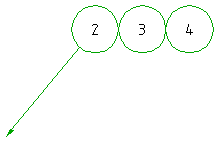
- The balloon circle must be the same size across all balloons within the drawing border.
- No geometry can intersect the balloon circle.
- The distance between the center points of adjacent balloons must be the same.
- The center point of all balloons in the collection must be aligned to each other.
- The leader must connect to the first or last balloon of the collection.


Rules for unique identifier
- Every drawing in the drawing project must have an identifier it. For example the part number of the part or assembly.
- The identifier must uniquely identify the part or assembly across all drawings in that project.
- For a given reference drawing and corresponding drawings:
- The identifier must be located in the same cell across all title blocks
- The identifier must be in the same column across all parts lists.
- If a drawing contains multiple drawing borders, the unique identifier must be the same across all title blocks in the drawing. In other words, the drawing borders must contain different views of the same part or assembly.