You can transform an image to correct distortions in distance and shape.
Image distortions can sometimes prevent you from aligning an image in your drawing. For example, correlation by scanning or matching may not work on aerial photographs that include distortions caused by parallax, unevenness of terrain, or lens distortion. In these cases, you can use rubbersheeting to permanently correct most of the distortions in an image.
Rubbersheeting uses a set of matched control points, consisting of source points in the image and destination points in the drawing. You can specify these points by picking them directly in the drawing, or by establishing a grid of destination points, to which you match source points. Once these control points are established, the image is transformed so that the points align as closely as possible.
There are two transformation methods you can use to correct your image:
- The Triangular method draws a series of triangles between the control points, then applies the transformation to those areas. This process uses the Delaunay triangulation method in which no point lies inside the circle that includes the vertices of any triangle. Each triangular area is transformed separately, so this method is much more accurate than the polynomial method, but can result in the loss of some image data. The area to be transformed, called the convex hull, is defined by the outermost destination points. Image data outside the convex hull is discarded. You can see which portion of the image will be transformed using the Preview. If you want to preserve more of the image data, place control points near the extents of the image.
- The Polynomial method transforms the entire image to match, as nearly as possible, the control points you specify. Unlike the triangular method, however, the actual destination points are not always located at the destination points you specified. The resulting positional error is expressed as a numerical value in the Rubbersheet dialog box, and is displayed graphically on the image after the control points have been entered. As shown in the following figure, the error for each point is measured as a distance from the intended destination point to the actual destination point.

The error is calculated using the following distance formula:
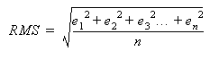
The total RMS (Root Mean Square) error of the image is calculated using the following formula:
By adjusting the polynomial degree, you can increase the accuracy of the matching points. However, reducing the error can create a higher degree of warping in the image as it is transformed to match the control points. Therefore, you should use the lowest possible polynomial degree that will still give you an acceptable result. Higher polynomial degrees result in smaller errors at the control points, but more warping at locations away from the control points.
| Number of Control Points | Maximum Polynomial Degrees |
|---|---|
| 3-5 | 1 |
| 6-9 | 2 |
| 10-14 | 3 |
| 15-20 | 4 |
| 21-27 | 5 |
AutoCAD Raster Design toolset does not limit the number of control points you can use.
The Preview tool allows you to see the extents of the transformed image before you actually apply the changes. The convex hull of destination points is displayed in red, while the convex hull of source points is shown in blue.
Using four points to rubbersheet (for example, four corners of an image) usually results in error at these points. In some applications, such as when rubbersheeted images will be tiled, this error may be unacceptable. To eliminate this error, you can change the polynomial equation so that a zero error condition results from the use of four points rather than three points. This change is made in the system registry. For complete instructions, go to the AutoCAD Raster Design toolset Support website (https://www.autodesk.com/rasterdesign-support) and search on the term “4 point rubbersheet”.