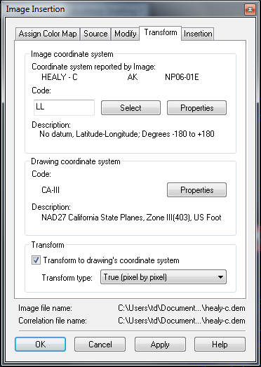
Use this tab to transform the coordinate system of an image to match the coordinate system used in a drawing file. In most cases, the system will select the correct code and related values for you. This tab is displayed if AutoCAD Raster Design toolset is installed on an Autodesk geographic application such as AutoCAD Map 3D toolset or AutoCAD Land Desktop or if a GIS coordinate system enabled drawing is opened.
- Enter Code
-
Enter the coordinate system code, if available. Doing this updates the Category and Coordinate System lists to identify the coordinate system specified by the code. After a code is entered, you can also click Properties to see more details about the coordinate system.
- Select Category From List
-
Displays the general category for the coordinate system, such as UTM or Lat Longs.
- Coordinate Systems in Category
-
Displays the specific coordinate system for the image.
- Transform To Drawing’s Coordinate System
-
Select this option to transform the image to the coordinate system used in the drawing, which is displayed here for reference.
- Transform Type
-
Select one of three options:
- True (pixel by pixel): produces the most accurate results.
- 4-Point Rubbersheet: approximate transformation, most accurate near the control points.
- 3-Point Affine: replicates the transformation performed on non-editable data types.
- OK
-
Verifies the transformation and inserts the transformed image into the drawing.
- Apply
-
Verifies the transformation and displays a preview of the transformed image.