In this exercise you learn how to vectorize linework with great precision, using AutoCAD Dynamic Input prompts.
Dynamic Input provides useful prompts of line lengths, angles, and command options in the vicinity of the cursor. This exercise involves setting the options for Dynamic Input, then vectorizing street edges and cul-de-sacs in a property drawing.
Related Exercises
Exercise
To configure Dynamic Input settings and vectorize linework
- In the \Tutorial6 folder, open the drawing file
VTools_Dyn.dwg.
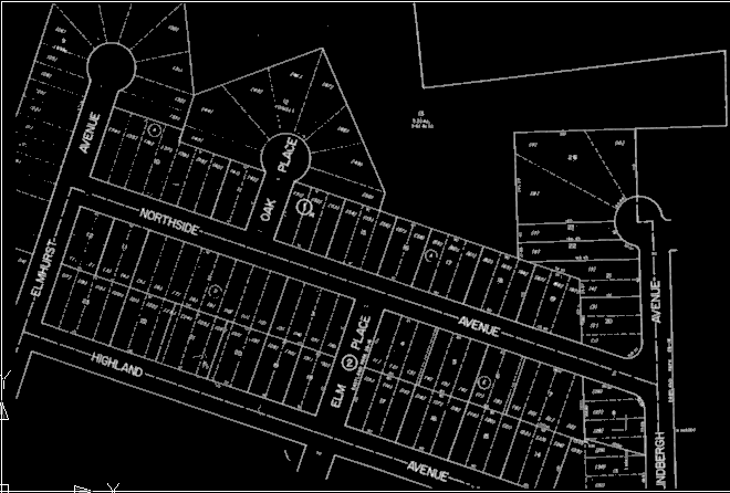
After setting some tool options, you can start vectorizing the street edges in this raster image.
- On the command line, enter the AutoCAD command OPTIONS.
- In the Options dialog box, on the Display tab, in the Window Elements area, select Show ToolTips; on the Drafting tab, in the AutoSnap Settings area, select Display AutoSnap Tooltip. Close the Options dialog box.
- Along the bottom of your drawing window, right-click DYN and click Settings. Alternatively, enter the AutoCAD command DSETTINGS.
- In the Drafting Settings dialog box, on the Dynamic Input tab, select all three options to enable Pointer Input, Dimension Input, and Dynamic Prompts.
- In the Pointer Input area, click Settings.
- In the Pointer Input Settings dialog box, in the Format area, select Polar Format and Absolute Coordinates; in the Visibility area, select Always. Click OK to close the dialog box.
- On the Dynamic Input tab, in the Dimension Input area, click Settings.
- In the Dimension Input Settings dialog box, click Show the Following Dimension Input Fields Simultaneously, and select Resulting Dimension, Absolute Angle, and Arc Radius. Click OK to close the dialog box.
- In the Drafting Settings dialog box, click Drafting Tooltip Appearance.
- In the Tooltip Appearance dialog box, click Colors.
- In the Drawing Window Colors dialog box, in the Context area, select 2D Model Space; in the Interface Element area, click Crosshairs; in the Color area, select a color such as Green that contrasts well with the white lines in the image. Click Apply & Close.
- In the Tooltip Appearance dialog box, click OK.
- In the Drafting Settings dialog box, on the Object Snap tab, select Object Snap On; in the Object Snap Modes area, select Endpoint and Intersection.
- In the
Drafting Settings dialog box, on the
Raster Snap tab, select
Raster Snap On; in the
Raster Snap Modes area, select
Center,
End, and
Corner; in the
Preferences area, select
Show Aperture and
Snap. Click
OK to close the dialog box.
Now you are ready to start vectorizing lines, beginning with the left (west) edge of Elmhurst Avenue. The following instructions use standard compass directions, assuming that the top of the image is north.
- Click
Raster menu
 Vectorization ToolsLine. Or enter the command vline.
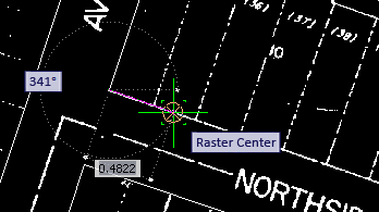
- Move the cursor to the west edge of Elmhurst Avenue, and snap to the center of the raster line. You should see the Raster Snap symbol and Raster Center tooltip to confirm this.
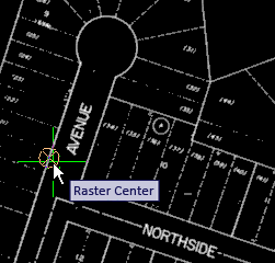
- Click to vectorize the line.
Tooltips show the line length and angle (252 degrees).
- Right-click and click Enter to vectorize the line.
- Move the cursor to the northeast side of Elmhurst Avenue, snap to the centre of this line, then click.
- Right-click and click Enter to vectorize the line, then right-click and click Cancel to end the command.
Tooltips show that the angle of this line is also 252 degrees. The presence of these two parallel vector lines provides a good base for vectorizing the cul-de-sac.
- Click
Raster menu Vectorization ToolsArc. Or enter varc.
The tooltip “Specify one-pick point or...” shows a Down Arrow icon. When you press the keyboard Down Arrow once, you see the two other options, Center and 3p; press again, and a black dot marks the first choice.
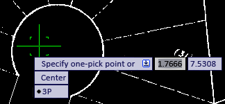
At this point, you can use the Up/Down Arrows to select an option. You can also select an option with the cursor, or right-click the mouse to select an option from the shortcut menu.
- Select the 3p option, then, as prompted, select the start point. Use the square Object Snap marker to select the end of the first vectorized line.
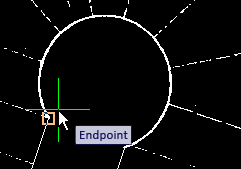
- Select another point along the arc, then select the third point at the end of the other street edge, using the Object Snap marker again. Press Enter to end the command.
In the next few steps, you will vectorize the rectangle bounded by Elmhurst, Highland, Northside, and Elm Place.
- Click
Raster menu Vectorization ToolsRectangle. Or enter vrect.
- Click the north corner of the rectangle, where Elmhurst meets Northside, and move the cursor a short distance to the southwest, along the east side of Elmhurst Ave.
Notice that the angle prompt is highlighted. In this state, you can lock the line to a specific angle by entering the numeric value.
- Enter 252, the angle you used for other edges of Elmhurst Ave.
- To specify the second corner point, click the diagonally opposite corner of the rectangle, where Highland and Elm Place meet.
- Right-click and click Enter, then right-click and click Cancel to end the command.
Note that the east and west corners of the rectangle are displaced from the raster corners. In a real project, you could decide at this point whether it is more important to follow the raster lines or keep the vector lines parallel.
Further exploration: To follow the raster lines, first click File menu
Undo. Do this one or more times to undo the vrect command, then use the polyline vectorization tool (vpline), with the 2p option, to vectorize the lines by clicking each corner point in a sequence around the rectangle, using the Object Snap marker to ensure that the start and end points join to form a closed figure.
In the next few steps, you will use the polyline vectorization tool to vectorize along Northside.
- Click
Raster menu Vectorization ToolsPolyline. Or enter vpline.
- Select the 2p option.
Tip: When using the 2p option to vectorize a polyline, click the start point, then click each vertex in sequence until you reach the endpoint.
- Click the end of the vector line at the corner of Elmhurst and Northside, and move the cursor a short distance east along Northside.
Notice that when you have two numeric prompts, such as angle and length, one of them is highlighted, indicating that you can enter a numeric value.
- Press the Tab key to switch the highlight from angle to length several times, then stop on angle.
- Enter 342, which is 90 degrees from the angle of Elmhurst (252 degrees), then press Tab to switch the highlight to the length value.
Now the angle is locked at 342.
- Slide the cursor east to the edge of Oak Place, click on the raster street edge, then follow this edge north east toward the cul-de-sac.
- At the Raster Corner prompt, click once to mark the endpoint, then right-click and click Enter.
You have finished the steps of this exercise, and should feel comfortable using the vectorization commands with Dynamic Input prompts.
Further exploration: Continue vectorizing more of the street edges in this image, deciding whether to lock angles or follow raster lines. After you vectorize both sides of Oak Place, use the Copy With Base Point command to copy the cul-de-sac from Elmhurst to Oak Place. With one of the arc endpoints as a base point, use Object Snap to attach the arc precisely to one street edge.
- Close the drawing without saving changes.