When Autodesk CAMplete TruePath is started for the first time, you will see the New Project wizard. This wizard allows you to begin a new project by selecting the CAM files (which contain the tool path information and cutting tool info, depending on the CAM system), the part and fixture geometry and the option cutting tool database (depending on the CAM system).
Creating a Project from the New Project wizard
-
When TruePath first starts, the New Project wizard will be displayed by default.
-
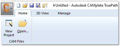
If the wizard does not start, click New Project on the Home tab of the ribbon:
-
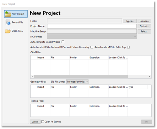
The New Project wizard contains 3 pages. The New Project page creates a fresh project, the Recent File page lets you selected previously loaded files and Open File lets you load a single file directly with a File Open dialog. Make sure that you are on the New Project:
-
The New Project page shows the following options:
Folder – The currently selected folder where all files will be imported from.
Types – Specify the file types to look for in the selected import folder.
Browse – Select the current import folder.
Project Name – The name of the new project document that will be created.
Output – Set the path and name for the CAMplete XML Project File.
Machine Setup – Lets you pre-select the machining setup that will be used for posting and simulation.
NC Format – Lets you pre-select the NC Format for posting.
Autocomplete Import Wizard – This option will skip the CAM Import Wizard (if the machining setup and NC Format have been pre-selected)
Auto Locate GCS to Bottom Of Part and Fixture Geometry – Will automatically align the bottom of the part and fixture to the project’s G-Code coordinates.
Auto Locate MCS to Pallet Top – Will automatically align the MCS to top of the pallet geometry.
CAM Files – The list of CAM CL data files that were found in the import directory.
Geometry Files – The list of geometry files that were found in the import directory.
Prompt for Units – This dropdown list controls how the geometry file units are handled.
Tooling Files – The list of tooling files that were found in the import directory.
-
Click Browse to select a folder**.
-
Select the folder where you want to import files from and click Select Folder:
-
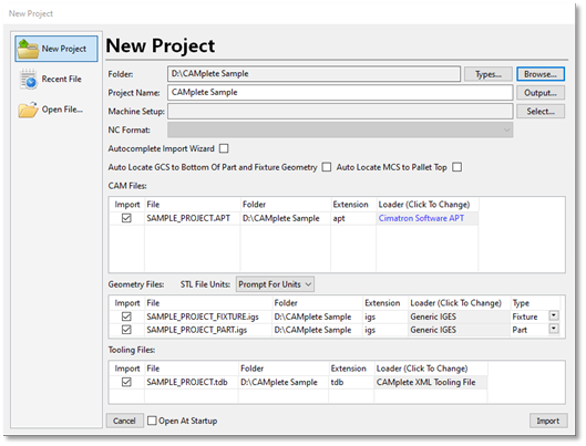
Autodesk CAMplete TruePath will scan the folder for files, which will appear in the grids:
-
For the CAM Files, each file will appear as an entry.
Import – Controls whether the file will be imported.
File – The name of the file.
Folder – The folder where the file exists.
Type – The identified type of file.
Loader – The kind of loader that will be used to load the file. To change the loader, click the button and select a new loader type from the applicable list:
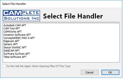 Note: For the example included with this guide, keep the setting as Generic APT.
 -
For the Geometry files, the grid will show each geometry file that was found:
Import – Controls whether the file will be imported.
File – The name of the file.
Folder – The folder where the file exists.
Extension – The identified type of file.
Loader – The kind of loader that will be used to load the file. To change the loader, click the button and select a new loader type from the applicable list.
Type – Controls whether the geometry will be added as the part geometry, fixture geometry or stock geometry. If the fixture geometry contains the text “fixture” in it’s name, it will be automatically set to the Fixture type.
-
For the Tooling files, the grid will show each tooling file that was found:
Import – Controls whether the file will be imported.
File – The name of the file.
Folder – The folder where the file exists.
Extension – The identified type of file.
Loader – The kind of loader that will be used to load the file. To change the loader, click the button and select a new loader type from the applicable list.
-
Once you have selected the files, click Import.
-
The file will be processed and the CAM Import Wizard will appear.
Starting a Project From a single CAM Tool Path File:
You can also begin a fresh project by just loading a single CAM file (for example: Mastercam NCI, Generic APT, UG NX CLS file, Esprit LST file, Powermill CUT and Hypermill POF)
-
After starting TruePath, you will see the simplified Home tab on the Ribbon.
-
Click Open to manually select the CAM file that you want to start with:
-
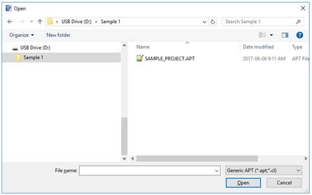
In the Windows Open dialog, navigate to the folder that contains your CAM file:
-
Switch the file type to the appropriate type for your CAM system. For this example, use Generic APT.
-
Select the file that you want to load and click Open.
-
The file will be processed and the CAM Import Wizard will appear.
Starting a Project From Multiple CAM Tool Path Files
You can also start a fresh project loading multiple CAM files at the same time (for example: Mastercam NCI, Generic APT, UG NX CLS file, Esprit LST file, Powermill CUT and Hypermill POF)
-
After starting TruePath, you will see the simplified Home tab on the Ribbon.
-
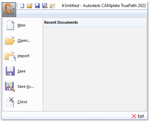
Click the C icon in the upper left, then select Import:
-
In the Windows Open dialog, navigate to the folder that contains your CAM file:
-
Switch the file type to the appropriate type for your CAM system. For this example, use Generic APT.
-
Select the file(s) that you want to load and click Open.
-
The file will be processed and the CAMImport Wizard will appear
Using the CAM Import Wizard
Once you have selected your files to use for your project, the files will be processed and the CAM Import Wizard will appear. This will let you set up the rest of your project. You can choose the construction of your programs, how they are posted and adjust cutting tool information.
CAM Import Wizard – Selecting the Machining Setup
The first step is to choose a Machining Setup, which is Autodesk CAMplete TruePath’s internal representation of a physical milling machine on your shop floor.
-
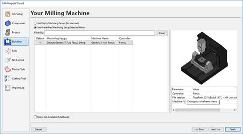
When starting a new project, the CAM Import Wizard always starts on the Machine page.
-
Select the option Use Predefined Machining Setup Selected Below.
-
Select your machine in the grid. As you select each machine, a preview of the machine will appear on the righthand side. To make the machine the default for the future, click the Default column next to the machine so that the check mark appears:
 Note: If you had previously selected a Default machining setup, it will automatically be selected in the grid and the Use Predefined Machining Setup Selected Below option will be selected.Note: The Show All Available Machines option will show all available machines that are in your machining setup directory and not just the machines that were manually imported through Resources > Machining Setup Manager > Import.
 -
Click Next or Files to access the File Parsing Options page.
CAM Import Wizard - Configure the File Parsing Options
The File Parsing Options allow you to control how operations generated in your CAM system will be structured in Autodesk CAMplete TruePath. You can select a structure that best fits how you want to treat your imported programs. In this example, you will post all of the imported operations as a single NC program; however, if you regularly run individual operations it may be more appropriate to treat each tool path as a separate NC program. You can also break each program into programs based on the tool number.
-
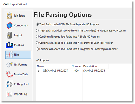
The File Parsing Options page will be displayed:
The file parsing options are:
Treat Each Loaded CAM File As A Separate NC Program – This will treat each individual CAM file as it’s own program.
Treat Each Individual Tool Path From The CAM File(s) As A Separate NC Program – This will turn every loaded operation into a separate program.
Combine All Loaded Tool Paths Into A Single NC Program – Combine all loaded operations (from all CAM files) into a single NC program.
Combine All Loaded Tool Paths Into A Program For Each Tool Number – Will create a program for each tool number found in the CAM files.
Combine All Loaded Tool Paths Into A Program For Program Number – Will create a program for each program number found in the CAM files.
-
Leave the setting as Treat Each Loaded CAM File As A Separate NC Program. This posts the entire demonstration project as a single program.
NOTE: At this point, you could also modify the program number and description in the NC Program grid. -
The NC Program tree shows how the programs and operations will look.
-
Click Next or NC Format to go to the NC Format page.
CAM Import Wizard - Select the NC Format
In Autodesk CAMplete TruePath, an NC Format controls the layout and additional codes and comments that need to be added to your posted program, while a machining setup controls the actual text of the G-Codes that are to be output. You can think of the combination of an NC format and a machining setup as being roughly equivalent to a traditional post processor. By separating these two functions, Autodesk CAMplete TruePath gives you increased flexibility and helps to standardize your manufacturing process as you expand and add new milling machines.
-
The NC Format page shows the program(s) in a grid with each operation:
 Note: The software will have automatically selected the first format that matches the NC control being used.
The upper grid shows the programs and operations and their current NC Format settings. The lower grid displays a summary of the currently selected program or operation. The Summary shows you how many planes, positions and cycles are in each operation. This can be used to determine if the correct path type is being used. To hide the summary, un-check the Show Summary button on the upper right.
-
Click the arrow button in the NC Format column for the main program (“Cube” in this example) to access the drop list.
-
Select the NC format to be used for all paths.
-
Selecting an NC format for the root item in the tree sets the NC format for all sub items. The NC formats can be set for individual sub items by clicking the button in the NC Format column for that item (this is not generally required).
-
Verify the type category (shown in the Type column) for each tool path.
The Type column controls whether the path is treated as 3+2 Axis or 5-Axis machining:
Type Description 3+2 Axis Machining If the orientation changes: -
Lift the tool from the part along the spindle axis
-
Reorient the tool to the part in a safe location
-
Perform a “safe” approach to machine on the next plane
5-Axis Machining Only perform an approach at the beginning of the path and retract at the end. All other orientation changes happen simultaneously (i.e., full simultaneous 5-Axis machining)
3/4-Axis etc. Depending on your machine, you might have other options available for manually controlling your NC Format. Refer to your reseller for help with setting up these options.
-
By analyzing orientation changes and other information in each tool path, Autodesk CAMplete TruePath determines if a tool path is most likely 3+2 Axis or 5-Axis. When you select any path in the top grid, the summary of orientation changes is shown in the **Summary of Path Positions** section. You can change the **Type** by selecting its drop list indicator in the column.-
Verify the Output Tool Reference category (shown in the Output Tool Ref column) for each tool path.
The output tool reference column controls whether the output G-Code is set to the tip of the cutting tool or the center of the cutting tool. It can be changed using the drop list for the column.
-
Verify the units (shown in the Units column) for each tool path.
The Units column controls whether the original data is in inches or millimeters. It can be changed using the drop list for the column.
-
Verify the input tool reference category (shown in the Input Tool Ref (CAM File) column) for each tool path.
The Input Tool Ref (CAM File) column specifies whether the original CAM file data is in tool tip or tool center coordinates. It does not need to be the same as the output tool reference and is usually controlled by the CAM system outputting the original file. It can be changed using the drop list for the column.
NOTE: If Force Tool Reference Values To Be The Same is selected then Output Tool Ref and Input Tool Ref (CAM File) cannot be changed independently. -
Review the tool name (shown in the Tool Name column) assigned to each tool path.
Note: The Tool Name column shows you information about the cutting tool created from the original CAM data. It is for reference only and cannot be changed. Cutting tools are changed on the Cutting Tool page of the CAM Import Wizard. -
When the NC Format is selected properly, click Next or Master/Sub to move to the Master/Sub page.
CAM Import Wizard – Set up a Master Program
Autodesk CAMplete TruePath allows you to specify that your loaded program is called by a “Master” program. Depending on your machine tool and controller, the settings on this page may not be relevant to your work environment. Ask your machine tool provider for more information on this option.
-
Each program is listed in the upper Sub-NC Program grid.
-
It can be assigned to as Master NC Program listed in the lower grid:
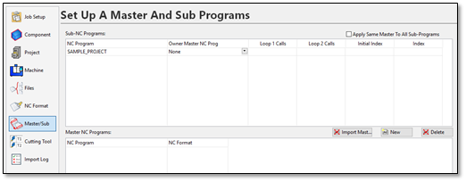 NOTE: Special NC Formats are required to use Master/Sub programs effectively. Contact your machine tool provider for more information.
 -
In this example, do not use any master programs or change anything on this page.
-
Click Next or Cutting Tools to access the Cutting Tool selection page.
To manage your imported cutting tools
Most CAM systems include cutting tool description information along with the CL data. Autodesk CAMplete TruePath reads this data and creates appropriate tools for each path. In addition to the tool geometry, Autodesk CAMplete TruePath assigns the tool identifiers to each tool and uses these when post-processing tool changes. Autodesk CAMplete TruePath also gives you the ability to define custom tooling with complex geometry (including tool holders) that is not exported by the CAM system. Using the CAM Import Wizard, you can select predefined cutting tools to use. The accuracy of the simulation and verification in Autodesk CAMplete TruePath depends on the tool and holder information accurately representing your actual tooling.
-
Each tool path is listed in the upper Tool Paths grid.
-
The lower Tool Changer grid shows all of the cutting tools:
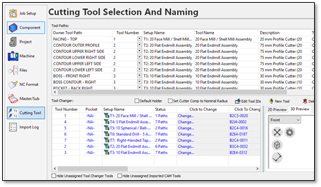
When you select a tool path in the upper grid, its associated tool is highlighted in the lower grid. The tool assignments for each tool path can be changed by using the Tool Number drop list in the Tool Paths grid.
Conversely, when you select a tool entry row in the lower grid, all tool paths in the upper grid that use that tool will be highlighted. The tool’s geometry is also displayed in the preview window. The tool number(s) can be edited in the Tool Number column of the Tool Changer grid.
You can select a tool from your database by clicking Change in the Click to Change column. You can change just the holder by clicking the Click To Change Holder column.
The Gauge Length (from the spindle gauge line to the tool center) and Extension Length (from the bottom of the tool holder to the tool center) can be edited in their columns. The Cutter Comp Radius value can be edited in its column and an individual Overcut Tolerance can also be set for each tool.
-
In this example, do not change anything on this page.
-
At this point, the project has been configured. Click Finish to complete the import process.
-
Your tool path data, part and fixture will now appear on the machine. After the machine is loaded, the program will be posted into G-Code. The progress for the posting will appear in the Regeneration Window:
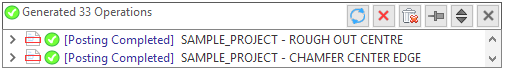
-
When the post processing is completed, (and there are no errors), this window will disappear after a short delay.