You can use the CAM Wizard to manipulate your project parameters in a single location.
-
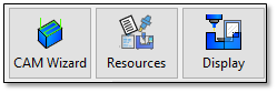
The CAM Wizard is displayed by clicking the button in the main Project Navigator view:
-
The CAM Wizard can also be accessed through the Ribbon:
-
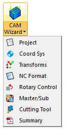
You can also access it through the CAM Wizard access button:
-
This ribbon item allows you to go directly to any page of the CAM Wizard directly.
-
Many of the options you originally set in the CAM Import Wizard can be reviewed and edited here.
-
In addition, the CAM Wizard provides access to the Coordinate Systems, Transforms, Rotary Axes and Summary pages, which are not available on the CAM Import Wizard.
CAM Wizard – Project Page
-
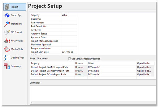
The Project page contains information about the project file:
-
The upper grid contains the project properties. These can be used to enter predefined information about the project file. This info will appear in the project summary and can be posted in your G-Code programs as comments.
-
The Project Directories grid shows the current input and output folder locations. By default, these directories are stored in the CAMplete project file. That way, when you are working with a particular project, it always remembers where the input and output locations were and will use those as the defaults.
a. Use Default Project Directories** – Enables the input/output file path tracking. When this is ON, when you input or output files, the Windows File dialogs will use the file path locations in the grid.
b. Property – Shows the name of each file path that can be modified.
Default Project CAM CL Path – Is the import file path that is used when you import CAM system data.
Default Project Geometry Path – Is the import file path that is used when you import fixture or part geometry.
Default Project GCode Export Path – Is the export file path that is used when you export your posted G-Code programs.
c. Browse – Click to change the location of the file path.
d. Value – The file path value.
e. Open Folder – Click to open the file path location in Windows File Explorer.
-
The Comments edit box lets you enter any generic text comments about the project.
CAM Wizard – Coord Sys Page
-
The Coord Sys page shows the current work datum assignments for the tool paths (operations) and the machine datums:

-
Tool Path Datum Settings shows the selected work datum for each Owner Tool Path (ie. Operation).
-
To change the work datum for an operation, change it with the drop list in the Type column.
-
All Available Datums on NC Controller lists the datums for the machine*. * (See Edit Datums – Page 6)
-
Visibility displays the Display Wizard – Datums page (See Display Wizard - Coord Sys - Page 6)
CAM Wizard – Transforms Page
-
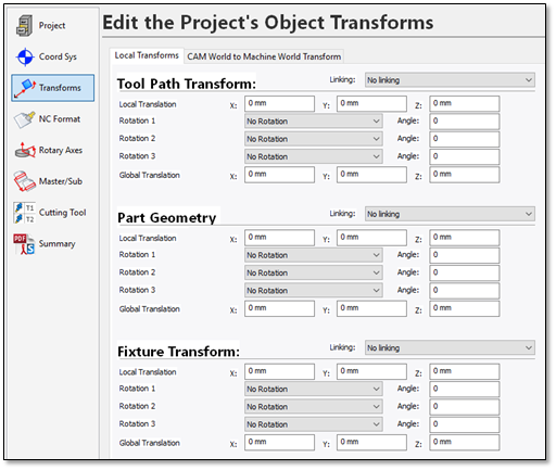
The Transforms page allows you to modify the location of the tool path (operation), part and fixture geometry:
-
By default, Autodesk CAMplete TruePath shows the Local Transforms tab. Autodesk CAMplete TruePath maintains local transforms for the fixture, part and tool paths. Transforms can be “linked” so that the same transform will be shared by multiple objects. The effect of modifying these transformations is seen in both Tool Positioning Mode and Machine Positioning Mode. For this example, there is no need to edit the Local Transforms.
-
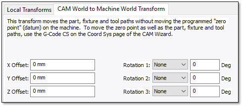
Click CAM World to Machine World System to see the global transformation of the entire project:
-
The global transformation edited on this page is applied to the fixture, part and tool paths and is measured relative to the G-Code coordinate system. This transformation will have an effect only in machine mode.
Warning: The transforms should ONLY be used when you want to shift your part without going back to the CAM systems. It should NOT be used to generally position your part for simulation since changes to the Tool Path and CAM World Transforms will alter the posted XYZ values.Note: For this example, do not use any transformations or modify any values on these pages.
CAM Wizard - NC Format Page
-
The NC Format page shows the program(s) in a grid with each operation:
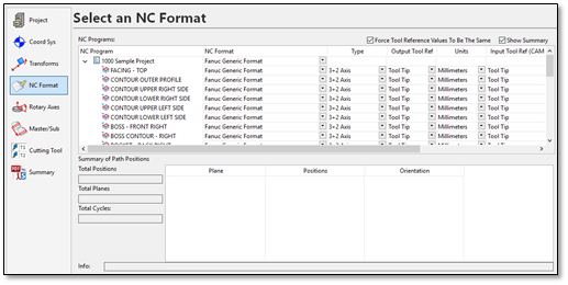
The upper grid shows the programs and operations and their current NC Format settings. The lower grid displays a summary of the currently selected program or operation. The Summary shows you how many planes, positions and cycles are in each operation. This can be used to determine if the correct path type is being used. To hide the summary, un-check the Show Summary button on the upper right.
-
To change and NC Format, click the drop list in the NC Format column for the main program and select the new format.
-
Selecting an NC format for the root item in the tree sets the NC format for all sub items. The NC formats can be set for individual sub items by changing the drop list in the NC Format column for that item (this is not generally required).
The Type column controls whether the path is treated as 3+2 Axis or 5-Axis machining:
Type
Description
3+2 Axis Machining
If the orientation changes:
1 - Lift the tool from the part along the spindle axis
2 - Reorient the tool to the part in a safe location
3 - Perform a “safe” approach to machine on the next plane
5-Axis Machining
1 - Only perform an approach at the beginning of the path and retract at the end. All other orientation changes happen simultaneously (i.e., full simultaneous 5-Axis machining)
3-Axis/4-Axis etc.
Depending on your machine, you might have other options available for manually controlling your NC Format. Refer to your reseller for help with setting up these options.
By analyzing orientation changes and other information in each tool path, Autodesk CAMplete TruePath determines if a tool path is most likely 3+2 Axis or 5-Axis. When you select any path in the top grid, the summary of orientation changes is shown in the Summary of Path Positions section. You can change the Type by selecting its drop list indicator in the column.
Output Tool Reference – The output tool reference column controls whether the output G-Code is set to the tip of the cutting tool or the center of the cutting tool. It can be changed using the drop list for the column.
Units – Controls whether the original data is in inches or millimeters. It can be changed using the drop list for the column.
Input Tool Ref (CAM File) – Specifies whether the original CAM file data is in tool tip or tool center coordinates. It does not need to be the same as the output tool reference and is usually controlled by the CAM system outputting the original file. It can be changed using the drop list for the column.
Tool Name – Shows information about the current cutting tool assigned to the operation. It is for reference only and cannot be changed. Cutting tools are changed on the Cutting Tool page of the CAM Import Wizard.
CAM Wizard – Rotary Axes Page
-
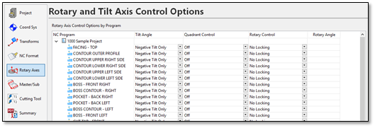
The Rotary Axes page lets you control the posting of the tilt and rotation angles:
-
Each program and tool path (operation) is listed in the grid.
-
Tilt Angle – Set the method for calculating the tilt angle:
Prefer Negative Tilt – Will use a negative tilt angle UNLESS the rotary axis will move longer than 180 degrees. In that case, it will switch to positive tilt so that the overall rotation is less.
Warning: Prefer Negative Tilt should usually be used with 5-axis tool paths only.Prefer Positive Tilt – Will use a positive tilt angle UNLESS the rotary axis will move longer than 180 degrees. In that case, it will switch to negative tilt so that the overall rotation is less.
Warning: Prefer Positive Tilt should usually be used with 5-axis tool paths only.Negative Tilt Only – Will ALWAYS use the negative tilt angle.
Positive Tilt Only – Will ALWAYS use the positive tilt angle.
NOTE: The default for the Tilt Angle is controlled by the NC Format. This column is for manually overriding these values. -
Quadrant Control – This option will override the tilt angle for 3+2 paths to choose the tilt angle that produces the most negative or positive solution in either the X or Y axis. This can be useful for machines with asymmetrical designs where collision might happen in certain locations on the machine.
a. Off – Quadrant control will not be used. The Tilt Angle column will control the tilt direction.
b. Choose Most X Positive – This option will calculate all XY positions in the path for the positive tilt. It will repeat this for the negative tilt. Then, it will choose the negative or positive tilt based on which solution produced the most positive X values.
c. Choose Most X Negative – This option will calculate all XY positions in the path for the positive tilt. It will repeat this for the negative tilt. Then, it will choose the negative or positive based on which solution produced the most negative X values.
d. Choose Most Y Positive – This option will calculate all XY positions in the path for the positive tilt. It will repeat this for the negative tilt. Then, it will choose the negative or positive tilt based on which solution produced the most positive Y values.
e. Choose Most Y Negative – This option will calculate all XY positions in the path for the positive tilt. It will repeat this for the negative tilt. Then, it will choose the negative or positive based on which solution produced the most negative Y values.
Note: When quadrant control is enabled, you cannot manually change the Tilt Angle column, since the quadrant control will override this. -
Rotary Control – Controls how the rotary axis behaves at the 3-axis solution (where the rotary axis can be any value).
a. No Locking – This will disable rotary axis control. In this case, the rotary axis will just use the last rotary axis angle from the previous operation or 0 if there was not previous operation.
b. Set Angle – Specify an angle for the rotary axis. This angle will be edited in the Rotary Angle column. This angle will be read from certain CAM systems.
c. Lock X at 0, Y Positive – This will lock the X-axis at 0 and spin the C-axis instead of outputting X motion. The Y axis will stay on the positive side.
d. Lock X at 0, Y Negative – This will lock the X-axis at 0 and spin the C-axis instead of outputting X motion. The Y axis will stay on the negative side.
e. Lock Y at 0, X Positive – This will lock the Y-axis at 0 and spin the C-axis instead of outputting Y motion. The X axis will stay on the positive side.
f. Lock Y at 0, X Negative – This will lock the Y-axis at 0 and spin the C-axis instead of outputting Y motion. The X axis will stay on the negative side.
Note: NC Format modifications will be required before using these options. Contact your machine reseller for more information.
CAM Wizard –Master/Sub Page
-
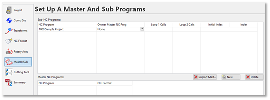
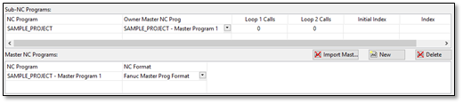
Each non-master program is listed in the upper Sub-NC Program grid.
-
It can be assigned to as Master NC Program listed in the lower grid using the drop list in the Owner Master NC Prog column:
-
The Master NC Programs grid shows all current Master programs in the project.
-
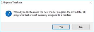
Click New to add a new one. You will be prompted to automatically assign any un-assigned sub-programs to the new Master program:
-
Answer Yes to this dialog.
-
The new Master program will be added to the lower grid. Its format will be set to the default for the project (if applicable). Also note that any sub-programs are now assigned to the new Master program:
-
The Master program will now appear in your Project tree and will be posted with the appropriate execution code.
CAM Wizard – Cutting Tool Page
-
The Cutting Tool page manages all cutting tools used in the project.
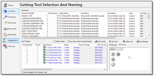
Each tool path (Operation) is listed in the upper Tool Paths grid. The lower Tool Changer grid shows all of the cutting tools:
When you select a tool path in the upper grid, its associated tool is highlighted in the lower grid. The tool assignments for each tool path can be changed by using the Tool Number drop list in the Tool Paths grid.
Conversely, when you select a tool entry row in the lower grid, all tool paths in the upper grid that use that tool will be highlighted. The tool’s geometry is also displayed in the preview window. The tool number(s) can be edited in the Tool Number column of the Tool Changer grid.
-
The Tool Paths grid has the following columns:
Owner Tool Path – The name of the tool path (operation).
Tool Number – The current tool assigned to that tool path (by its tool number). Use the drop list to select a different tool from the tool changer list. You cannot edit the tool number in this entry, only select a different tool from the tool changer list. To edit the tool number of a tool, use the Tool Number column in the tool changer grid.
Setup Name – The name of the currently assigned tool assembly (for reference only).
Tool Name – The name of the currently assigned cutter (for reference only).
Description – The description of the currently assigned tool (for reference only).
Type – The type of the currently assigned tool (for reference only).
Tool Edge – The currently assigned tool edge (for machines with turning capability).
X Offset – The X Offset for turning tools (for machines with turning capability).
Y Offset – The Y Offset for turning tools (for machines with turning capability).
Rotation Angle – The spindle rotation angle for turning tools (for machines with turning capability).
-
The Tool Changer grid lists all available tools in the project (it emulates the machine’s tool changer). It has the following columns:
Tool Number – The current tool number. Can be edited to be any valid tool number or tool id tag that the machine will support.
Pocket – The pocket number (for machines that support this feature).
Setup Name – The current name of the tool (this is automatically generated based on the tool database name/CAM data name and the tool number).
Status – Lists how many tool paths use the given tool.
Click To Change – Select a different tool assembly from CAMplete’s tool library.
Click To Change Holder – Select a different tool holder from CAMplete’s tool library.
Edit Setup – Edit the tooling setup directly.
Gauge Length – The current length of the tool from the spindle gauge line to the tool tip. This can be edited to control the tool stick-out distance. When this edited, the Extension Length will be recalculated automatically.
Extension Length – The current stick-out distance of the tool from the end of the holder to the tool tip. When this edited, the Gauge Length will be recalculated automatically.
Cutter Comp Radius – Specifies the radius to use when simulating 2D cutter compensation. This is set to 0 by default which simulates wear compensation.
Override Overcut Tol – Allows you specify a different overcut tolerance for the tool (this overrides the value entered on the Collision Checking option).
Overcut Tol – The value of the overridden overcut tolerance.
Tool Name – The name of the tool assembly.
Description – Description of the tool assembly.
Type – The type of cutting tool
-
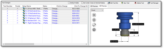
When you select a tool in this grid, it will appear in the 3D Preview:
-
This 3D view can be orbited and scaled using the standard TruePath 3D view mouse commands (middle button for orbit, mouse wheel for zoom).
-
The 3D buttons in this view are as follows:

Autoscale the view

Switch the view to wireframe mode

Toggle the 3D dimensions

Access the display settings for the 3D preview. This lets you change the background color and the dimension colors.
-
Default Holder – Enable this option to have CAMplete choose a default holder (which must be specified in the machining setup).
-
Set Cutter Comp to Nominal Radius – Set every tool’s Cutter Comp Radius to its nominal radius. This will simulate using geometry radius cutter compensation.
-
Edit Tool IDs– Edit the custom tool id’s to support machines that can have both tool numbers and tool names.
-
New Tool – Create a new tool and add it to the tool changer.
-
Delete Tool – Delete the currently selected tool(s) from the tool changer. (Note that you cannot delete a tool that is assigned to a tool path).
-
Tool Manager – Launch the CAMplete Tool Manager view.
CAM Wizard – Summary Page
Autodesk CAMplete TruePath provides a summary of all your important project information, including general project information, statistical information about your NC programs and information you can use to set up your machine and tooling.
-
On the Home tab of the Ribbon, click Summary:
 Note: The Summary button also appears on the Programs tab of the Ribbon
 -
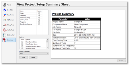
The CAM Wizard will be displayed, showing the Summary page:
-
Each category of the summary sheet is listed in the upper left grid. Selecting a row, shows that summary category options and a preview. Categories can be removed from the setup sheet by unchecking its Export option.
-
The available categories are:
Project – The main project information including the generation date, the Autodesk CAMplete TruePath version info and the overall project summary (number of tools, number of programs, number of tool paths, etc.).
Geometry – Information about the fixture and part geometry.
Machining Setup – The machine description and the various offsets and transforms used.
Cutting Tools – The list of cutting tools used, including the total cutting time.
Programs – Individual summary of each program and tool path including the cutting times, datums, units, tool selection, 2D cutter compensation (D-Code), tool length compensation (H-Code), spindle speed(s), feed rate(s) and minimum and maximum feeds.
Coordinate Systems – Detailed outputs of the coordinate systems (datums) used in the project.
-
Click Export to save the summary. You can output the summary to an HTML file that can be loaded into a web browser or spread sheet program. Or you can output the summary as a PDF with 3D screen shots of major project items.
The Options Templates can be used to save and load summary settings. To create a template, select the options you want, click Save and enter an XML file name for the template. That template will now appear in the drop list and can be selected from there at any time. To remove a template, select it in the drop List and click Delete.