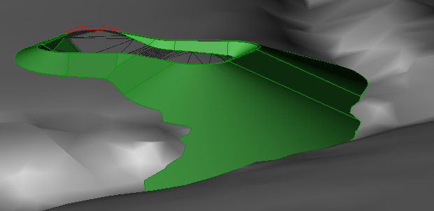
Autodesk Civil 3D slope grading uses a technique known as boundary representation, or b-Rep modeling. For each segment of the footprint, a bounded cone, plane, or spline region is created to match the grading criteria for that segment. These pieces are intersected against each other, and the resulting pieces are joined together in order to create a grading with real 3D intelligence.

Figure 9: Corner of a large projection grading
Figure 9 shows exactly how the cone on the outside corner of a pond intersects with the surface. Notice that you cannot draw a straight projection line from the footprint to the part of the grading that flows along the valley in the lower left. A simple ray projection algorithm would not generate this part of the solution, because it would find only the first ray intersection with the surface, at a higher elevation. By showing accurate results of the grading criteria, Autodesk Civil 3D makes it easier for engineers to see important details and explore realistic design options. For example, in this case we can see that a retaining wall could prevent the grading from flowing along the valley, and we could revise the design to include such a wall.
Finding a good solution becomes more difficult if the grading segments do not intersect each other fully. Autodesk Civil 3D uses straightening and averaging algorithms to handle these and other problem spots in a second computing pass. While the 2D daylight is reasonably clear in most cases, finding the complete 3D edited solution can be much more complicated. Another complicating factor is the limited precision with which computers can calculate intersections. For these reasons, short segments and shallow angles can also be problematic.