You can create a custom expression for flow in a full circular pipe.
To create the expression
- In Toolspace, on the Settings tab, expand a pipe label style collection.
- Right-click Expressions and click New.
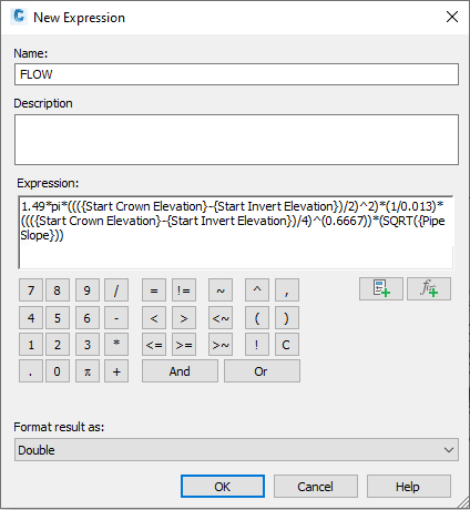
- In the New Expression dialog box, enter the name as FLOW.
- Enter the following expression:
1.49*pi*((({Start Crown Elevation}-{Start Invert Elevation})/2)^2)*(1/0.013)*((({Start Crown Elevation}-{Start Invert Elevation})/4)^(0.6667))*(SQRT({Pipe Slope}))
- Click OK.

Figure 11: Flow capacity expression
The term ((Start Crown Elevation – Start Invert Elevation)/2) has been substituted for Pipe Radius. The use of Pipe Radius, which is a named component of the pipe, does not work correctly in this case. Similarly, do not use the {Inner Pipe Diameter} component.
This expression assumes a Manning’s “n” value of 0.013, which is the standard for concrete pipe. In fact, pipes have a named component for Manning’s “n” value, which you can set. However, adding that component to your expression yields an undesired result, so you should not use it for this procedure.
Create Flow Label Style
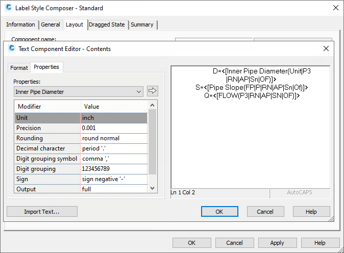
The next step is to create a pipe label style for plan and profile that displays this value for flow. Figure 12 shows an example of this label style with all the pertinent hydraulic settings:

Figure 12: Use the text component editor to display flow capacity (Q)
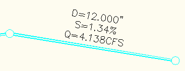
Display the flow capacity for design purposes. When you want to produce your construction plans, assign a style more suitable for production drawings. As pipes are created and labeled, the label style DESIGN FLOW will display the flow capacity (Q) of the pipe.

Figure 13: Flow capacity label
The flow capacity label is especially effective in profile view where you can adjust the invert grips of each pipe until the desired pipe capacity is reached. You may need to follow each iteration of invert raising or lowering with a REGEN command to regenerate the drawing.
You can create pipe and structure tables in Autodesk Civil 3D. Now, with the added expression for flow, you can easily add the capacity of a pipe to a table.
These expressions demonstrate the importance of fully exploring the capability of mathematical expressions with Autodesk Civil 3D. Making a couple of assumptions, it is easy to see that any user with a simple understanding of Manning’s equation can create an expression for flow capacity and compare that value to the expected flow calculated by the design storm. Then the user can use this comparison to help set the diameter and slope of a pipe.