Sometimes, inside corners are not well suited to a projection grading solution. In reality, the projection grading result is often different from what will be constructed in the field. Let’s look at a building footprint example to illustrate a technique for using the best of both feature line tools and projection grading tools.
The exercises described in this section are also available in the form of two detailed Grading tutorials: Tutorial: Grading from a Complex Building Footprint and Tutorial: Using Feature Lines to Modify a Grading.
We start with a building pad that already has the basic elevations assigned. In this case, the top portion of the pad is at an elevation of 402 feet and the bottom portion is at 400 feet.
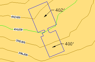
Figure 18: Building pad overview
In this case, let’s assume that we want to create a 1.5-foot shoulder around the pad, and then grade into the existing ground surface at –1%. At first, it might seem like slope grading is the ideal choice for both of these tasks; however, the area around the ramp needs more control than slope grading alone can provide. Let’s look at what happens when we try to apply the first criteria to this footprint, grading to a distance of 1.5 feet.
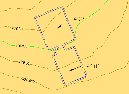
Figure 19: Building pad with slope grading
The 2D view in figure 19 looks fine, but notice in the 3D view of figure 20 how the grade twists in near the ramp:
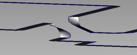
Figure 20: Grade twists beside the ramp
Because the ramp is steeper than the specified 1% cross-slope, there is no good way for slope grading to resolve this condition within the given constraints. More importantly, the inner portion of the shoulder is now substantially steeper than 2:1, so the problem will be exaggerated when we try to grade to the surface.
What we need is more detailed control of this region than slope grading allows. Because the daylight of a slope grading is controlled entirely by the criteria, it cannot be edited except by changing the criteria of the grading. Instead, we can use the Stepped Offset command to generate a daylight line that we can edit manually to resolve the area around the ramp. First, we run the stepped offset command with the same parameters that were given to the slope grading (1.5' at –1%). This initial step yields essentially the same daylight solution as the slope graded version. However, because this is a stepped offset, we can use the full set of feature line editing tools to refine the solution. Next, we use the feature line Fillet command with a radius of 15' to create a smooth fillet between the corners of the two pads, as shown in figure 21.
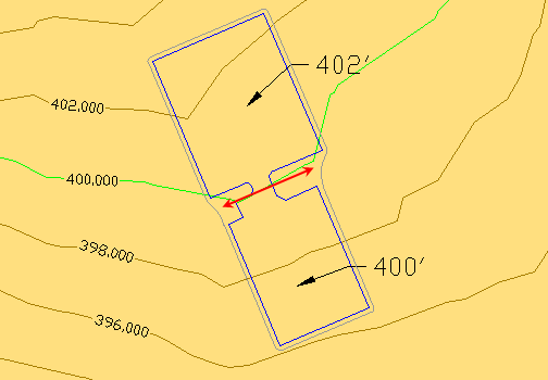
Figure 21: Fillets inserted on each side of the ramp
Notice that the feature line fillet uses the elevations from the existing feature line, and smoothly interpolates them across the length of the fillet, as shown in figure 22.
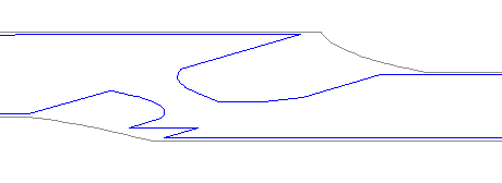
Figure 22: Fillet elevations
Note that we could have used several other feature line editing tools to trim out this portion of the grading and set the desired elevations for the shoulder edge.
Now that we have a smoother feature line to grade from, we apply a 2:1 grade-to-surface criteria and create infill grading objects to handle the interior parts. Each infill grading must be completely bounded by feature lines. Figure 23 clearly shows the diamond markers for the two infill grading objects: one for the building pads and the ramp between them, the other for the perimeter of both pads and the area between the fillets and the ramp.
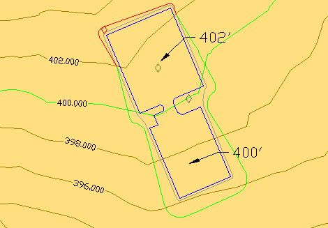
Figure 23: Project graded to the surface
Figure 24 shows the same grading in a 3D shaded view. The gray area (1) is the infill grading that represents the shoulder, the gold area (2) is the pad infill grading, and the green (3) is the slope grading to the surface.
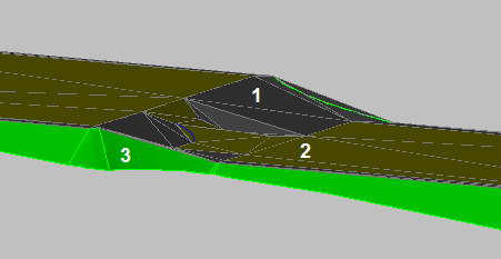
Figure 24: 3D grading
There are several more details to clean up:
- The arc portion of our ramp (area 1 in figure 25) is not triangulated very well.
- One of the triangles adjacent to the ramp (area 2) is too steep.
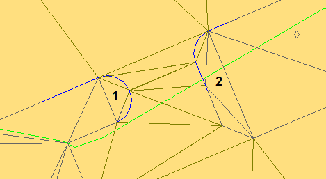
Figure 25: Triangulation issues
To fix the arc triangulation, we need to set a finer value for tessellation spacing in the grading group. As shown in figure 26, this can be difficult to find in the Grading Group Properties dialog box, because it can be set only when Automatic Surface Creation is enabled. However, this setting is also used for the Create Detached Surface command and infill grading triangulation. The best solution at this point is to turn on Automatic Surface Creation, change the tessellation spacing from the default value of 10 feet to 1 foot, then turn off Automatic Surface Creation again. You must click Apply after turning on Automatic Surface Creation in order to apply the changed settings.
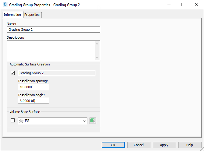
Figure 26: Changing tessellation spacing
With the tessellation spacing set correctly, you need to update the infill grading. The easiest way to do this is by selecting the interior feature line (the building pad), and using MOVE with a displacement of (0.0, 0.0, 0.0). The results are shown in figure 27.
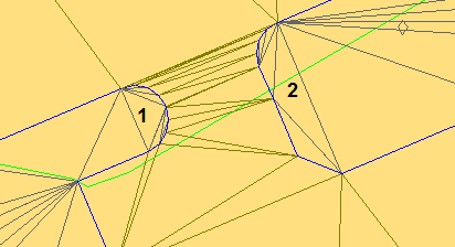
Figure 27: Improved triangulation on one side
The arcs in the ramp (area 1) are now triangulated better, but the triangles on the right side (2) are not well distributed. To handle this last issue, we will add another feature line to the infill, using the feature line to control the elevations in the same way that a breakline is used in a surface.
First, create a polyline in the area that needs to be fine-tuned.
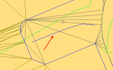
Figure 28: Feature line insertion
Then use the Create Feature Lines From Objects command. In this case, we want to assign elevations from grading objects so that the new feature line starts at reasonable elevations. There is no need to insert intermediate grade break points. The triangulation of the infill adjusts to accommodate the new feature line, as shown in figure 29. You can use any of the feature line editing tools to precisely control this portion of the infill grading.
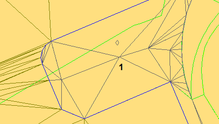
Figure 29: Resolved triangulation
Figure 30 shows the 3D view of our edited grading.
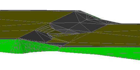
Figure 30: Final result in 3D
By using feature lines and projection grading skills together, we have demonstrated how to work through a typical design process, creating an initial grading, and then optimizing it for the specific project terrain.
As demonstrated in this process, after you understand the grading design concepts, and master the basic procedures, you can combine projections with feature lines, and use a range of operations to resolve the design challenges of a particular project.