The interaction of one grading with another grading makes tying in design objects easier. As discussed in the previous example, the design goal is to integrate a pond grading in this area with the adjacent parking lot.
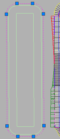
Figure 37: Creating a feature line from the pond’s outer polyline
Grading from Pond Feature Line
In this example, to begin the design of the pond, the Create Feature Lines from Objects command is used to select the outermost pond polyline as shown in figure 38.
Then, we can use the Elevation Editor to set the feature line elevation. We apply an elevation so that the pond is in close proximity to the corridor feature line elevation. Then, we can use the grading creation tools to tie the pond feature line in at a 3:1 slope.
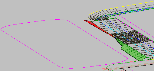
Figure 38: 3D view of the pond feature line next to the parking lot grading
The feature line represents the top of the pond so we need to connect it to the existing ground. To grade the feature line, for the example shown here, we set the Site to Pond, the grading group to Storm Pond, and the target surface to EG. Then, we apply a grade to the entire length of the new (pond) feature line, using a 3:1 grade-to-surface criteria.
After the grading calculation has been completed, notice that the intersecting slopes between the pond and parking lot have cleaned themselves up, providing a grading solution that requires no additional work.
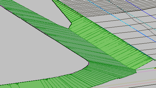
Figure 39: Integrated pond and parking lot slopes
Now we can complete the design of the pond. Next we apply a Grade to Distance criteria using a distance of 10-feet and a grade of -2 to create a ten-foot wide area which forms the berm of the pond.
Next we specify a Grade to Relative Elevation criteria with a difference of -12 and slope of 3:1 to grade from the berm to what will be the pond bottom. The resulting slope descends 12-feet to define the depth of the pond, as shown in figure 40.
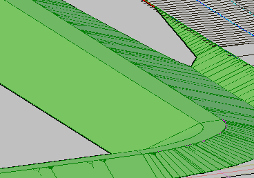
Figure 40: Pond slopes graded to distance and elevation
The last step is to use the Create Infill command to add a bottom to the pond. Note that an infill can only be used to fill an area that is enclosed by feature lines. The pond bottom is completed, as shown in figure 41.
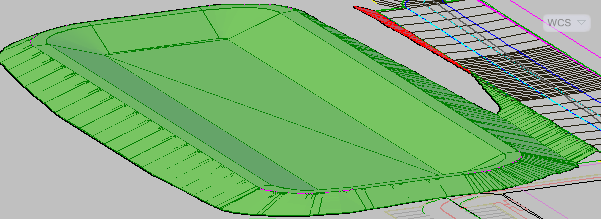
Figure 41: Grading infill is the bottom of the pond
Grading Volume Tools
Use the Grading Volume Tools to view the cut and fill results for your design. These tools can help you to quickly complete a design such as a detention pond. When the grading is completed, you can incrementally raise and lower the pond, updating the volume calculations each time. There is also a tool that will balance the earthwork for this grading group.
Size by Volume
If you are designing a detention pond and want to size it by volume, it may help to create a temporary surface to use as the Volume Base Surface for comparison. To do this, draw a polyline around the pond rim, assign it the rim elevation, and add it as breakline data to a surface. When you use such a surface as the Volume Base Surface for the grading group, you can more easily see how much volume the pond can contain.
Remember that Automatic volume balancing is an iterative process. If the initial result is not satisfactory, you can adjust the gradings up or down in smaller increments until you achieve the target volume.
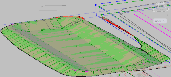
Figure 42: The volume tools adjust the cut and fill and balance the grading group
In the past, cleaning up between gradings would have been the designer's responsibility, but now Autodesk Civil 3D completes this task. In addition, you can use the Grading Volume Tools to quickly analyze and adjust different design scenarios.