The following sections describe best practices for displaying pipe networks in profile and section views.
Pipe Appearance in Section View
Pipe sections are drawn using the FACETDEV (Facet Deviation) system variable. This variable controls the smoothness (tessellation) of curved edges of the pipes in section view.
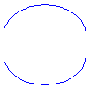
The default value of FACETDEV will usually cause pipe sections to be displayed in section views with line segments, rather than as smooth curves. The following illustration shows an elliptical culvert in section view when FACETDEV is set to 0.5 feet.

If you set FACETDEV lower, to 0.01 for example, the appearance of the pipe sections will become more circular, as shown in the following illustration.

The number you specify for facet deviation defines the maximum distance from the chord to the arc—the chord being an edge that is created from faceting the curve to the true mathematical arc. The facet deviation has a range of greater than zero (0) and no upper limit. The lower this variable is set, the more segments will be used to draw the pipe. The minimum number of segments is 8.
The maximum number of facets is controlled by the FACETMAX variable. This variable can be set from 100 to 10,000. Note that using a small value for FACETDEV and a large value for FACETMAX will adversely affect drawing performance.
FACETDEV and FACETMAX are Autodesk Civil 3D variables (rather than AutoCAD variables). They are therefore not listed when using the AutoCAD command SETVAR.
To change the FACETDEV variable
- At the command line, enter FACETDEV.
- At the Set New Facet Deviation prompt, enter 0.01. Adjust the value to a smaller number if greater smoothness is required.
Pipe Connection Display in Profile
Use the Clean Up Pipe To Pipe Connections option in the Pipe Style dialog box, as shown in figure 4, to improve the appearance of pipe profiles so that the pipes graphically appear to line up as expected. This option is not enabled by the default, so you must select it.
To enable pipe clean up
- Select a pipe in the drawing.
- Right-click and click Edit Pipe Style.
- Select the Profile tab in the Pipe Style dialog box.
- Select the Clean Up Pipe to Pipe Connections check box.

Figure 4: Dialog box for selecting pipe connection clean up
Create From an Alignment
Creating an alignment from network parts is a good method for generating pipe run profiles. If your local agency standards require profiles for pipe network centerlines, use the Create Alignment From Network command to convert alignments to networks.
Grip Editing in Profile View
When grip editing pipes and structures in profile view, a good practice is the use of the transparent command station/elevation. This is useful if you need to set a grip (Pipe ends/Structure rim or sump) at a certain elevation. You can also match the crown invert of adjacent pipes across structures. In general, grip editing enables you to more easily modify slopes and elevations.
Convert 3D Polylines
A good method for creating water and gas line pipe profiles is to create a 3D polyline and then convert it to a pipe network.
To convert a 3D polyline
- Use the Survey feature to convert survey data to a 3D polyline object.
- Use the Create Pipe Network From Object command to convert the 3D polyline into a pipe network.
Based on the vertices of the 3D polyline, Autodesk Civil 3D will place structures on the network.