The following sections describe good practices that will help avoid mistakes when getting started with drawings.
Prevent Scaling
If you are using a 3D drawing, insert your 3D survey drawing into this file. You must ensure that the units of measure are not accidentally scaled to another unit. For example, if your drawing uses imperial units, it may accidentally be scaled to metric. To prevent scaling, set the INSUNITS value to 0.
Use References to Reduce Drawing Size
Create a surface directly from the point file rather than importing the points as COGO points. This practice avoids the use of system memory to keep the point data labels up to date. Rather than starting a design in the same drawing as the surface, create a data shortcut to the surface. This practice will dramatically reduce the active drawing size.
Apply Meaningful Names to Objects
Adopt a naming convention that applies useful names to differentiate objects. Because multiple people in your company may work with your drawings, it is important to use consistent and meaningful names.
Use Minimal Object Styles
For most efficient processing, use styles that have very little or no displayed elements. Minimal display styles draw faster, and are especially relevant for large objects, such as surfaces, point groups, and corridors.
Minimal display styles are useful in conceptual designs, the early stages of a project, and whenever you want to suppress the display of a surface or other large object. They can also apply to other objects, subject to the nature of your drawings. Minimal styles for objects, such as surfaces and corridors, should be configured in both 2D and 3D display modes for efficient use.
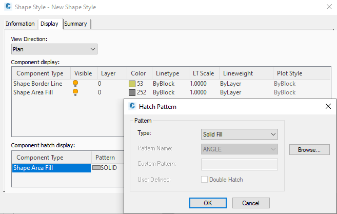
When designing corridors, you can create more efficient subassemblies by ensuring that the shape style for each one is defined with no fill, or at least with a solid fill rather than hatch patterns. Figure 2 shows the Shape Style dialog box, where you can define a subassembly shape style.

Figure 2: Editing a subassembly shape style
Turn Off Labels
As with object styles, you can design separate label styles for use at different project stages, and for different audiences. For example, an empty “No Label” style is useful, especially for alignments, profile views, and other objects with label sets. You can switch off all labels for an object by applying this style. You can turn off labels to reduce clutter and drawing time for some design phases.
To turn off all labels for a feature:
- Right-click the feature node on the Toolspace Settings tab.
- Click Edit Label Style Defaults.
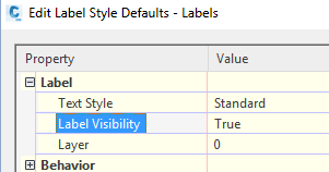
- In the Edit Label Style Defaults dialog box, set label visibility to false, as shown in figure 3.

Figure 3: Turning off label visibility for a feature
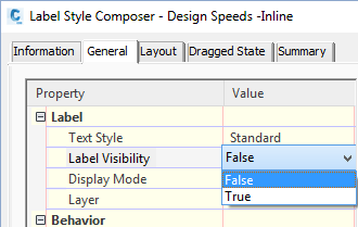
If you want to create a label design that has just the essential data and can be drawn quickly, simplify all text and graphic elements, including the use of rotation, borders, and plan readability. Another useful tactic is to leave a style in place, but temporarily edit the style with the Label Style Composer to turn off the label visibility, as shown in figure 4.

Figure 4: Turning off label visibility
Use of Layers to Manage Display
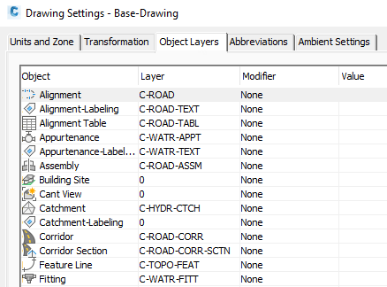
For faster processing, freeze or turn off the drawing layers that contain objects. By default, design objects and their labels are divided across multiple layers. For example, as shown in figure 5, alignments, profiles, and other road design objects are spread across many layers, all beginning with C-ROAD. If you consolidate the road design objects on fewer layers, it is easier to turn them on or off.

Figure 5: C-ROAD layers
From The Ground Up
Jack Strongitharm, an Autodesk Civil 3D Application Engineer for the UK and Ireland, has contributed some good ideas to this section. See Jack’s blog for more tips and tricks at: http://fromthegroundup.typepad.com/from_the_ground_up/