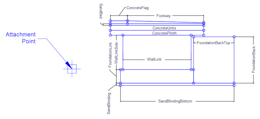
The RailPlatform subassembly includes common layers for rail platform such as walls, concrete plinth, footway, sand bed, foundation, and so on.
Attachment
Input Parameters
|
Parameter |
Description |
Type |
Default |
|---|---|---|---|
| Side | Specifies which side to place the subassembly. | Left / Right | Right |
| Wall Width | Width of the wall below the rail platform | Numeric, positive |
2.782 ft 0.85 m |
| Wall Link Code | A list of codes to be assigned to the wall link | Comma-separated string | Wall |
| Concrete Plinth Height | Height of the concrete plinth above the wall | Numeric, positive |
0.2 ft 0.06 m |
| Concrete Plinth Link Code | A list of codes to be assigned to the Concrete Plinth link | Comma-separated string | Concrete Plinth |
| Concrete Units Height | Height of the concrete units above the concrete plinth | Numeric, positive |
0.2 ft 0.06 m |
| Concrete Flag Link Code | A list of codes to be assigned to the Concrete Flag link | Comma-separated string | Concrete Flag |
| Concrete Units Shape Code | A list of codes to be assigned to the Concrete Units shape | Comma-separated string | Concrete Units |
| Concrete Flag Shape Code | A list of codes to be assigned to the Concrete Flag shape | Comma-separated string | Concrete Flag |
| Concrete Flag Height | Height of the concrete flag above the concrete units | Numeric, positive |
0.12 ft 0.04 m |
| Concrete Flag Width | Width of the concrete flag above the concrete units | Numeric, positive |
0.7 ft 0.21 m |
| Concrete Units Link Code | A list of codes to be assigned to the Concrete Units link | Comma-separated string | Concrete Units |
| Sand Bed Depth | The depth of the sand between the concrete units and concrete flag | Numeric, positive |
0.07 ft 0.02 m |
| Sand Bed Shape Code | A list of codes to be assigned to the sand bed shape | Comma-separated string | Sand |
| Wall Shape Code | A list of codes to be assigned to the Wall shape | Comma-separated string | Wall |
| Sand Bed Link Code | A list of codes to be assigned to the Sand Bed link | Comma-separated string | Sand |
| Concrete Plinth Shape Code | A list of codes to be assigned to the Concrete Plinth shape | Comma-separated string | Concrete Plinth |
| Footway Slope | Slope of footway on the rail platform | Numeric | 40 ( :1 ) |
| Footway Shape Code | A list of codes to be assigned to the Footway shape | Comma-separated string | Footway |
| Foundation Shift | Distance from the concrete wall to the foundation | Numeric |
0.1 ft 0.03 m |
| Foundation Depth | Depth of the rail platform | Numeric, positive |
0.556 ft 0.17 m |
| Foundation Shape Code | A list of codes to be assigned to the Foundation shape | Comma-separated string | Foundation |
| Overhang | Distance of the rail platform from the concrete wall on both sides | Numeric |
0.512 ft 0.156 m |
| Foundation Link Code | A list of codes to be assigned to the foundation link | Comma-separated string | Foundation |
| Foundation Back Width | Width of the foundation back | Numeric, positive |
1.65 ft 0.5 m |
| Foundation Back Shape Code | A list of codes to be assigned to the Foundation Back shape | Comma-separated string | Foundation Back |
| Footway Link Code | A list of codes to be assigned to the Footway link | Comma-separated string | Footway |
| Sand Blinding Depth | Depth of sand blinding under the rail platform | Numeric, positive |
0.1 ft 0.03 m |
| Sand Blinding Shape Code | A list of codes to be assigned to the sand blinding shape | Comma-separated string | Sand Blinding |
| Foundation Back Height | Height of the foundation back | Numeric, positive |
1.05 ft 0.32 m |
| Platform Edge Feature Line Code | A list of codes to be assigned to the Platform Edge Feature Line link | Comma-separated string | PlatformEdge |
| Platform Height Above Top of Rail | Adjusts the elevation of the platform above the Top of Rail (Origin Point of Subassembly) | Numeric |
0.2 ft 0.6096 m |
Target Parameters
| Parameter | Description | Status |
|---|---|---|
| OffsetFromCL | Offset From Rail Centerline | Optional |
| PlatformElevation | Height Above Rail | Optional |
Runtime Logical Assignments
None.
Output Parameters
None.
Behavior
This subassembly provides a rail platform that attaches to a rail alignment. Place the platform subassembly insertion point on the centerline alignment and profile of the rail and adjust the behavior by setting the input parameters and optional target parameters listed above.
Layout Mode Operation
In layout mode, this subassembly draws the rail platform.
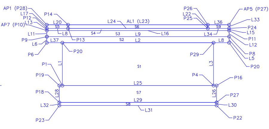
Point, Link, and Shape Codes
The following table lists the point, link, and shape codes for this subassembly that have codes assigned to them. Point, link, or shape codes for this subassembly that do not have codes assigned are not included in this table.
|
Point, Link, or Shape |
Code |
Description |
|---|---|---|
| P1 | WallBottomLeft | Wall Bottom Left |
| P2 | WallTopLeft | Wall Top Left |
| P3 | WallTopRight | Wall Top Right |
| P4 | WallBottomRight | Wall Bottom Right |
| P5 | PlinthBottomLeft | Plinth Bottom Left |
| P6 | PlinthTopLeft | Plinth Top Left |
| P7 | PlinthTopRight | Plinth Top Right |
| P8 | ConcreteUnitsTopLeft | Concrete Units Top Left |
| P9 | ConcreteUnitsTopRight | Concrete Units Top Right |
| P10 | SandBedTopLeft | Sand Bed Top Left |
| P11 | SandBedTopRight | Sand Bed Top Right |
| P12-P13 | PlatformEdge | Platform Edge |
| P14 | PlatformEdgeBottom | Platform Edge Bottom |
| P15 | Top, FootwayRightEdge | Footway Right Edge |
| P16 | FoundationRightEdge | Foundation Right Edge |
| P17 | FoundationBottomRight | Foundation Bottom Right |
| P18 | FoundationBottomLeft | Foundation Bottom Left |
| P19 | FoundationEdgeLeft | Foundation Edge Left |
| P20 | PlinthBottomRight | Plinth Bottom Right |
| P21 | SandBlindingRightTop | Sand Blinding Right Top |
| P22 | SandBlindingRightBottom | Sand Blinding Right Bottom |
| P23 | SandBlindingLeftBottom | Sand Blinding Left Bottom |
| P24 | FoundationBackTopLeft | Foundation Back Top Left |
| P25 | FoundationBackTopRight | Foundation Back Top Right |
| L1 | WallLinkSide | Wall Link Side |
| L2 | WallLinkTop | Wall Link Top |
| L3 | WallLinkSide | Wall Link Side |
| L4 | WallLinkBottom | Wall Link Bottom |
| L5 | ConcretePlinthLink | Concrete Plinth Link |
| L6 | ConcretePlinthLinkTop | Concrete Plinth Link Top |
| L7 | ConcretePlinthLink | Concrete Plinth Link |
| L8 | ConcretePlinthLinkBottom | Concrete Plinth Link Bottom |
| L9 | ConcreteUnitLink | Concrete Unit Link |
| L10 | ConcreteUnitLinkTop | Concrete Unit Link Top |
| L11 | ConcreteUnitLink | Concrete Unit Link |
| L12 | ConcreteUnitLinkBottom | Concrete Unit Link Bottom |
| L13 | SandBedBottomLeft | Sand Bed Bottom Left |
| L14 | SandBedLinkTop | Sand Bed Link Top |
| L15 | SandBedBottomRight | Sand Bed Bottom Right |
| L16 | SandBedLinkBottom | Sand Bed Link Bottom |
| L17 | ConcreteFlagLink | Concrete Flag Link |
| L18 | ConcreteFlagLink, Top | ConcreteFlagLink, Top |
| L19-L20 | ConcreteFlagLink | Concrete Flag Link |
| L21 | Footway, Top | Footway |
| L22 | FootwayLink | Footway Link |
| L23 | FootwayLinkBottom | Footway Link Bottom |
| L24 | FootwayLink | Footway Link |
| L25-L28 | FoundationLink | Foundation Link |
| L29 | SandBlindingTop | Sand Blinding Top |
| L30, L32 | SandBlinding | Sand Blinding |
| L31 | SandBlindingBottom | Sand Blinding Bottom |
| L33, L35 | FoundationBack | Foundation Back |
| L34 | FoundationBackTop | Foundation Back Top |
| L36 | FoundationBackBottom | Foundation Back Bottom |
| S1 | Wall | Wall |
| S2 | ConcretePlinth | Concrete Plinth |
| S3 | ConcreteUnits | Concrete Units |
| S4 | SandBed | Sand Bed |
| S5 | ConcreteFlag | Concrete Flag |
| S6 | Footway | Footway |
| S7 | Foundation | Foundation |
| S8 | SandBlinding | Sand Blinding |
| S9 | FoundationBack | Foundation Back |
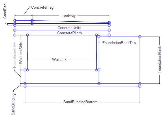
Coding Diagrams