The Internal_Multi_Track subassembly is used for a single railroad that includes sleepers, ballast, subballast, and two additional layers or materials which can be used for Sub Base and Soil Fill material.
The dimensions of the Internal_Multi_Track rails can be edited as well as the dimensions of the material layers.
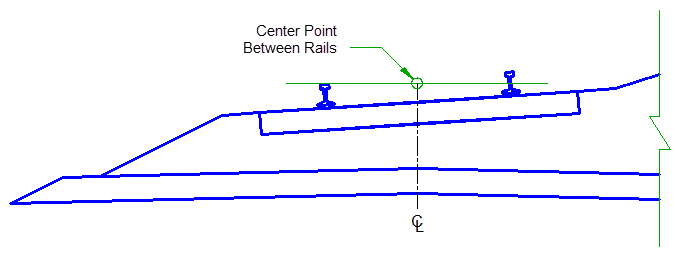
Attachment
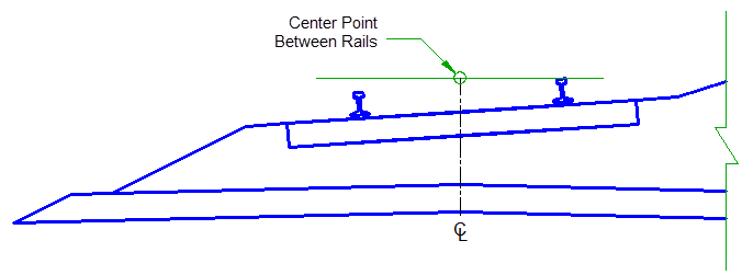
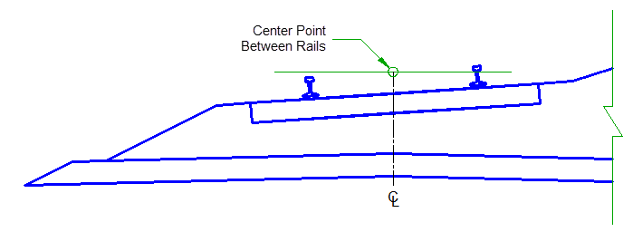
By default, the attachment point is at the centerline between the rails. The track can be moved relative to this point using the subassembly parameters.
Input Parameters
|
Parameter |
Description |
Type |
Default |
|---|---|---|---|
| Measure Cant At | Determines whether the elevation difference between rails takes place between the gauge line (face) of each rail or CL of each rail. | Selection List:
|
CL Rail to CL Rail |
| Default Cant | The default elevation difference between rails. The value is positive when the right rail is higher than the left and negative when the right rail is lower than the left. This value is applied in layout mode and is helpful for observing how the subassembly reacts to different cant values. This value is overridden by cant when it is present via the baseline alignment. | Numeric | 0 |
| Drainage Channel Depth | Depth of right drainage channel from top of ballast. | Numeric, non-negative |
0.5 ft 0.1524 m |
| Gauge | The distance between the inside faces of the rails | Numeric, non-negative |
56.5" 1435 mm |
| Rail Head Width | Width of the rail head. | Numeric, non-negative |
2.72" 69 mm |
| Rail Depth | Depth of rail from top of rail to top of tie plate | Numeric, non-negative |
6.625" 168 mm |
| Rail Base Width | Width of the base of the rail | Numeric, non-negative |
5.5" 140 mm |
| Tie Plate Thickness | Thickness of the tie plate which is also the distance from the bottom of the rail to the top of the tie. | Numeric, non-negative |
1" 25 mm |
| Rail Base to Ballast | Distance from the bottom of the rail to the top of the ballast. If this value is equal to the tie plate thickness, then the top of the ballast is flush with the tops of the ties. | Numeric, non-negative |
1" 25 mm |
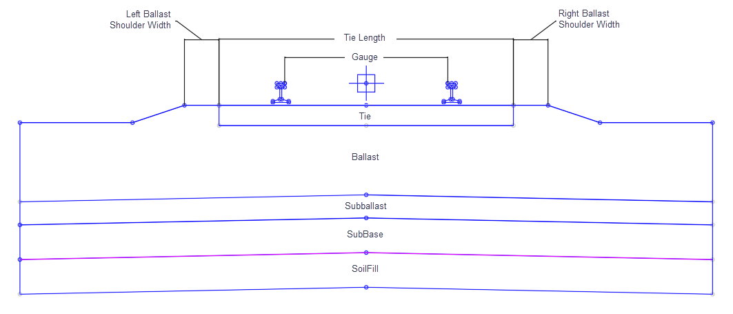
| Tie Length | Length of the tie (also known as sleeper). | Numeric, non-negative |
8.5' 2.59 m |
| Tie Depth | Depth of tie | Numeric, non-negative | 7"
178 mm |
| Minimum Ballast Depth | The minimum vertical distance between the bottom of the tie and the top of the subballast. The location of this minimum distance changes at different stages in cant. See Behavior below. | Numeric, non-negative | 12"
305 mm |
| Ballast Shoulder Width (Left and Right) | The distance from the end of the tie to the beginning of the ballast side slope. | Numeric, non-negative | 12"
305 mm |
| Ballast Side Slope (Left and Right) | The slope of the side of the ballast material. The slope of the top of the ballast material matches the slope of the tie that results from cant. | Slope, non-negative | 2:1 |
| Subballast Depth | The depth of the subballast material | Numeric, non-negative | 8"
203 mm |
| Subballast Top Slope (Left and Right) | The top slope of the left and right sides of the subballast with the centerline of the subassembly as the hinge point. | Slope, non-negative | 40:1 |
| Subballast Side Slope | The slope of the side of the subballast material. | Slope, non-negative | 2:1 |
| SubBase Extension | The distance from the toe of the subballast material to the beginning of the side slope of the subbase material | Numeric, non-negative |
0.5 ft 0.15 m |
| SubBase Slope | The slope of the side of the SubBase material. | Slope, non-negative | 1:1 |
| SubBase Depth | The depth of the SubBase material | Numeric, non-negative |
1 ft 0.30 m |
| Soil Fill Depth | The depth of the Soil Fill material | Numeric, non-negative |
1 ft 0.30 m |
| Soil Fill Slope | The slope of the side of the Soil Fill material. | Slope, non-negative | 1:1 |
| Soil Fill Extension | The distance from the toe of the subbase material to the beginning of the side slope of the Soil Fill material | Numeric, non-negative |
0.5 ft 0.15 m |
| Omit Rails | Prevents the rail points, links, and shapes from being drawn. | Yes/No | No |
| Omit Tie | Prevents the tie points, links, and shapes from being drawn. | Yes/No | No |
| Omit Ballast | Prevents the ballast points, links, and shapes from being drawn. If this option is set to Yes then the subballast is also not drawn. | Yes/No | No |
| Omit Subballast | Prevents the subballast points, links, and shapes from being drawn. If the Omit Ballast option is set to Yes then the subballast is not drawn regardless of this setting. | Yes/No | No |
| Omit SubBase | Prevents the subbase points, links, and shapes from being drawn. If the Omit Ballast or subballast option is set to Yes then the Sub Base is not drawn regardless of this setting. | Yes/No | No |
| Omit Soil Fill | Prevents the soil fill points, links, and shapes from being drawn. If the Omit Ballast, subballast, or subbase option is set to Yes then the soil fill is not drawn regardless of this setting. | Yes/No | No |
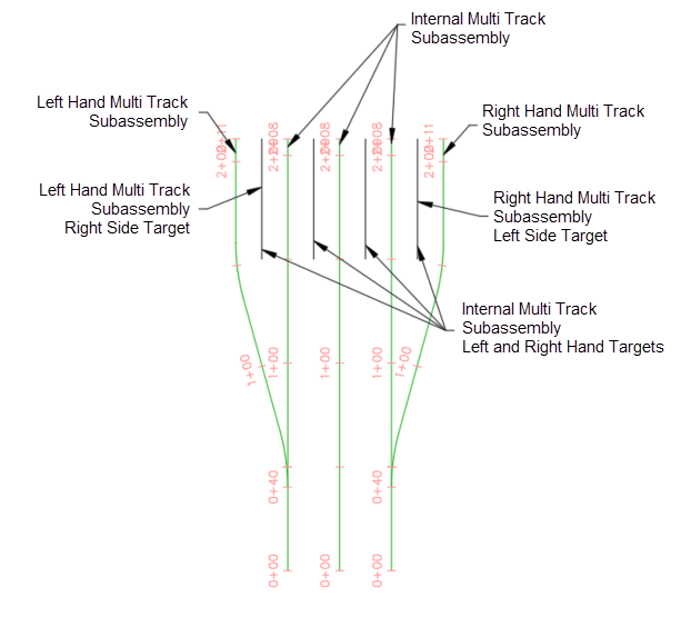
Target Parameters
This section lists the parameters in this subassembly that can be mapped to one or more target objects. For more information, see To Specify Corridor Targets.
|
Parameter |
Description |
Status |
|---|---|---|
| RightSideOffset | Right Side Offset | Optional |
| RightSideElevation | Right Side Elevation | Optional |
| LeftSideOffset | Left Side Offset | Optional |
| LeftSideElevation | Left Side Elevation | Optional |
Runtime Logical Assignments
None.
Output Parameters
None.
Behavior
If you set the Pivot Method to High Side Rail, then the rail on the outside of the curve is held at track elevation and the elevation of the inside rail is adjusted an amount equal to the cant value.
If you set the Pivot Method to Center Baseline, then both rails are adjusted an amount equal to half the cant value, the outside rail upward and inside rail downward.
The Minimum Ballast Depth value applies at the location of the minimum clearance between the tie and subballast. The Subballast Top Slope parameter independently controls the subballast top slope . The Baseline to Subballast Crown parameter controls the location of the subballast crown.
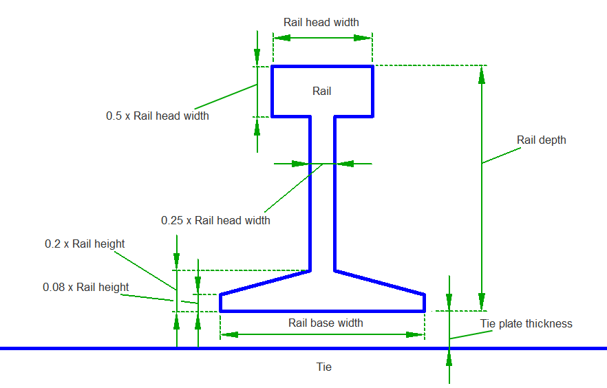
Rail Detail
The rail shape used in this subassembly is a simplified approximation of industry standard rail shapes and dimensions. Rail Head Width, Rail Depth, and Rail Base Width are available as input parameters and are used to derive the remaining approximated dimensions.
Layout Mode Operation
In layout mode the subassembly displays the links comprising the rails, tie, ballast, subballast, and side slopes.
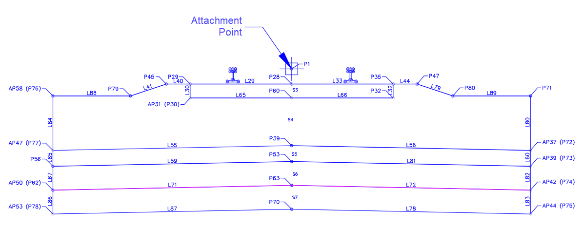
Point, Link, and Shape Codes
The following table lists the point, link, and shape codes for this subassembly that have codes assigned to them. Point, link, or shape codes for this subassembly that do not have codes assigned are not included in this table.
|
Point, Link, or Shape |
Code |
Description |
|---|---|---|
| P1, P4-P27, P58-P59 | Rail | Rail |
| P2 | Cl_Rail | Centerline of Rail |
| P3 | Gauge_Line,Rail | Gauge line (inside edge of top of rail) |
| P28-P32, P60 | Tie | Tie |
| P54-P55, P45, P47, P71-P72, P76 | Ballast | Ballast |
| P53, P73 | Subballast | Subballast |
| P62-P63, P74 | SubBase | SubBase |
| P70, P75, P78 | Soil Fill | Soil Fill |
| L1, L2 | Top_Rail, Rail | Top of rail |
| L3-L28 | Rail | Rail |
| L29-L33, L65-L66 | Tie | Tie |
| L40-41, L44, L55-L56, L63, L79-L80, L84, L88-L89 | Ballast | Ballast |
| L59-L60, L81, L85 | Subballast | Subballast |
| L67, L71-L72, L82 | SubBase | SubBase |
| L78, L83, L86-L87 | Soil Fill | Soil Fill |
| S1, S2 | Rail | Rails |
| S3 | Tie | Tie |
| S4 | Ballast | Ballast |
| S5 | Subballast | Subballast |
| S6 | SubBase | SubBase |
| S7 | SoilFill | SoilFill |
Coding Diagram