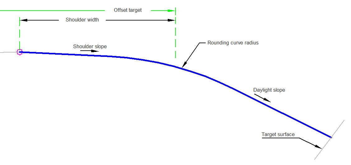
The ShoulderRoundedTarget subassembly provides rounding of a shoulder.
The shoulder is measured from the attachment point to the PVI of the rounding. If the distance between the PVI and the target surface is not adequate to provide the rounding curve, the rounding curve value is reduced to fit. You can define the geometry of the rounded shoulder.
Attachment
The attachment point is at the inside edge of the paved shoulder, which is typically at the outside edge-of-traveled way.
Input Parameters
|
Parameter |
Description |
Type |
Default |
|---|---|---|---|
| Side | Specifies which side to place the subassembly. | Left/Right | Right |
| Shoulder Slope | Slope of the shoulder. | Numeric | -5 ( % ) |
| Daylight Slope | The slope for the daylight slope. | Numeric, positive | 2 (: 1) |
| Rounding Curve | Specifies value for length. | Numeric, positive |
2.5 ft 0.75 m |
| Shoulder Width | Width from the attachment point to the shoulder hinge point. | Numeric, positive |
5 ft 1.5 m |
Target Parameters
This section lists the parameters in this subassembly that can be mapped to one or more target objects. For more information, see To Specify Corridor Targets.
|
Parameter |
Description |
Status |
|---|---|---|
|
Daylight Surface |
Name of the daylighting surface. The following object types can be used as targets for specifying the surface: surfaces. | Optional |
|
Offset Target |
May be used to override the shoulder width and tie the shoulder width to an offset alignment. The following object types can be used as targets for specifying the offset: alignments, polylines, feature lines, or survey figures. | Optional |
Runtime Logical Assignments
None.
Output Parameters
None.
Behavior
The PVI location of the rounded curve is calculated by using the input parameters or, if set, the Offset Target. A temporary daylight link is then calculated. Then the curve is calculated and the remaining points and links are added to the subassembly.
Layout Mode Operation
In layout mode the subassembly displays the links comprising the shoulder.
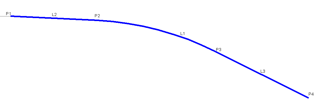
Point, Link, and Shape Codes
The following table lists the point, link, and shape codes for this subassembly that have codes assigned to them. Point, link, or shape codes for this subassembly that do not have codes assigned are not included in this table.
|
Point, Link, or Shape |
Code |
Description |
|---|---|---|
| P1 | Top, Hinge | |
| P4 | Daylight, Top | |
| L1 - L3 | Top |
Coding Diagram