The SideSlopeCutDitch subassembly inserts links to create an optional ditch and then daylights to cut and fill.
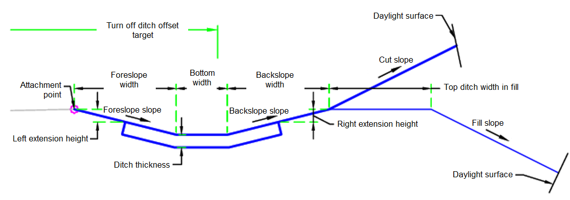
Attachment
The attachment point is at the inside edge of the initial cut or fill slope. This component can be attached to either the left or right side.
Input Parameters
|
Parameter |
Description |
Type |
Default |
|---|---|---|---|
| Side | Specifies which side to place the subassembly | Left / Right | Right |
| Daylight Link | Includes or omits the Daylight link | Yes / No | Yes |
| Ditch Lining Shape Code | Controls the shape code of the ditch lining | String | Concrete |
| Ditch Thickness | Thickness of material of the ditch | Numeric, positive |
0.5 ft 0.15 m |
| Use Ditch in Fill | Controls whether a ditch is created in the fill condition | Yes / No | Yes |
| Backslope Width | Width of the ditch backslope link (cut only) | Numeric, positive |
4 ft 1.2 m |
| Backslope Slope | Slope of the ditch backslope link (cut only) | Numeric | 4 ( : 1 ) |
| Bottom Width | Width of the bottom of ditch | Numeric, positive |
2 ft 0.6 m |
| Foreslope Width | Width of the ditch foreslope link (cut only) | Numeric, positive |
4 ft 1.2 m |
| Foreslope Slope | Slope of the ditch foreslope link (cut only) | Numeric | 4 ( : 1 ) |
| Fill Slope | Slope of the daylight link for fill | Numeric | 4 ( : 1 ) |
| Cut Slope | Slope of the daylight link for cut | Numeric | 4 ( : 1 ) |
| Right Extension Height | Distance to start of channel right side lining | Numeric, positive |
0.5 ft 150 mm |
| Top Ditch Width in Fill | The width of the link at the top of the ditch in fill | Numeric, positive |
3 ft 1 m |
| Left Extension Height | Distance to start of channel left side lining | Numeric, positive |
0.5 ft 150 mm |
Target Parameters
This section lists the parameters in this subassembly that can be mapped to one or more target objects. For more information, see To Specify Corridor Targets.
|
Parameter |
Description |
Status |
|---|---|---|
| Daylight Surface | Name of the daylighting surface. The following object types can be used as targets for specifying the surface: surfaces. | Required |
| Omit Ditch | May be used to turn off the construction of the ditch. The following object types can be used as targets for specifying this offset: alignments, polylines, feature lines, or survey figures. | Optional |
Runtime Logical Assignments
None.
Output Parameters
None.
Behavior
The initial hinge point is set at the attachment point. The hinge point elevation is checked against the target surface to determine if the section is in the cut or fill condition.
If the parameters require a ditch, the ditch is built using the input parameters. If the Omit Ditch target is found, then the ditch will not be built. The ditch lining, if the ditch thickness is greater than 0, is built. If the ditch is in fill, the top ditch width in fill is applied.
The ditch hinge point is checked against the target surface to determine if the section is in the cut or fill condition. Then the daylight link is created using the appropriate Fill Slope and Cut Slope.
If no ditch is required, the daylight link is created using the appropriate Fill Slope and Cut Slope.
Layout Mode Operation
In layout mode, this subassembly draws the initial fill slope to 5 units.
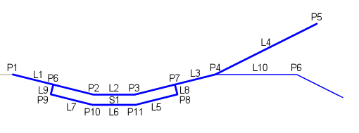
Point, Link, and Shape Codes
The following table lists the point, link, and shape codes for this subassembly that have codes assigned to them. Point, link, or shape codes for this subassembly that do not have codes assigned are not included in this table.
|
Point, Link, or Shape |
Code |
Description |
|---|---|---|
| P2 | Ditch_In | Inside of ditch |
| P3 | Ditch_Out | Outside of ditch |
| P4 | Hinge, Hinge_Cut, Hinge_Fill | Hinge point, either cut or fill |
| P5 | Daylight, Daylight_Cut | Daylight point in cut |
| P6 | Hinge, Hinge_Fill | Hinge point in fill |
| P7 | Daylight, Daylight_Fill | Daylight point in fill |
| P8-P11 | DitchBottom | Bottom of ditch |
| L1-L3, L10 | Top, Ditch | Top of ditch |
| L4 | Top, Daylight, Daylight_Cut | Daylight link in cut |
| L5-L7 | Datum, Ditch_Bottom | Bottom of ditch |
| L11 | Top, Daylight, Daylight_Fill | Daylight link in fill |
| S1 | Ditch Lining Shape Code | User input value |
Coding Diagram